Power transmission line dip measurement method

a technology of power transmission lines and dip measurement, applied in the direction of mechanical measuring arrangements, instruments, using mechanical means, etc., can solve the problems of increasing errors, increasing measurement errors, and difficult maintenance of accuracy, so as to minimize measurement errors

Active Publication Date: 2010-06-03
KPS CO LTD
View PDF2 Cites 21 Cited by
  • Summary
  • Abstract
  • Description
  • Claims
  • Application Information

AI Technical Summary

Benefits of technology

[0010]Therefore, the present invention has been made in view of the above problems, and it is an object of the present invention to provide a power transmission line dip measurement method that is capable of automatically calculating the operating amount of a measurement instrument to a dip point using a vector calculation equation in which power line support points of two steel towers and the dip point are displayed as a space vector, thereby minimizing a measurement error.

Problems solved by technology

In the indirect type power line dip measurement using the tangent of the power line, however, all the processes are carried out on the steel towers, with the result that errors may be increased.
In addition, the maintenance of accuracy is difficult due to the slope of the steel towers and complicated structure of the steel towers, with the result that measurement errors may be increased.
Also, the workers must climb up several positions of the steel towers according to the positions of power lines, with the result that it is difficult to secure the safety of the workers, and therefore, the workers may be exposed to danger.
Also, it is difficult to perform accurate power line dip measurement and maintain the dip of the constructed power line for each phase and for each conductor.
Furthermore, the dip difference between conductors may cause short circuits of wires.

Method used


Image

  • Power transmission line dip measurement method
  • Power transmission line dip measurement method
  • Power transmission line dip measurement method

Examples


Embodiment Construction

[0025]Now, preferred embodiments of the present invention will be described in detail with reference to the accompanying drawings.

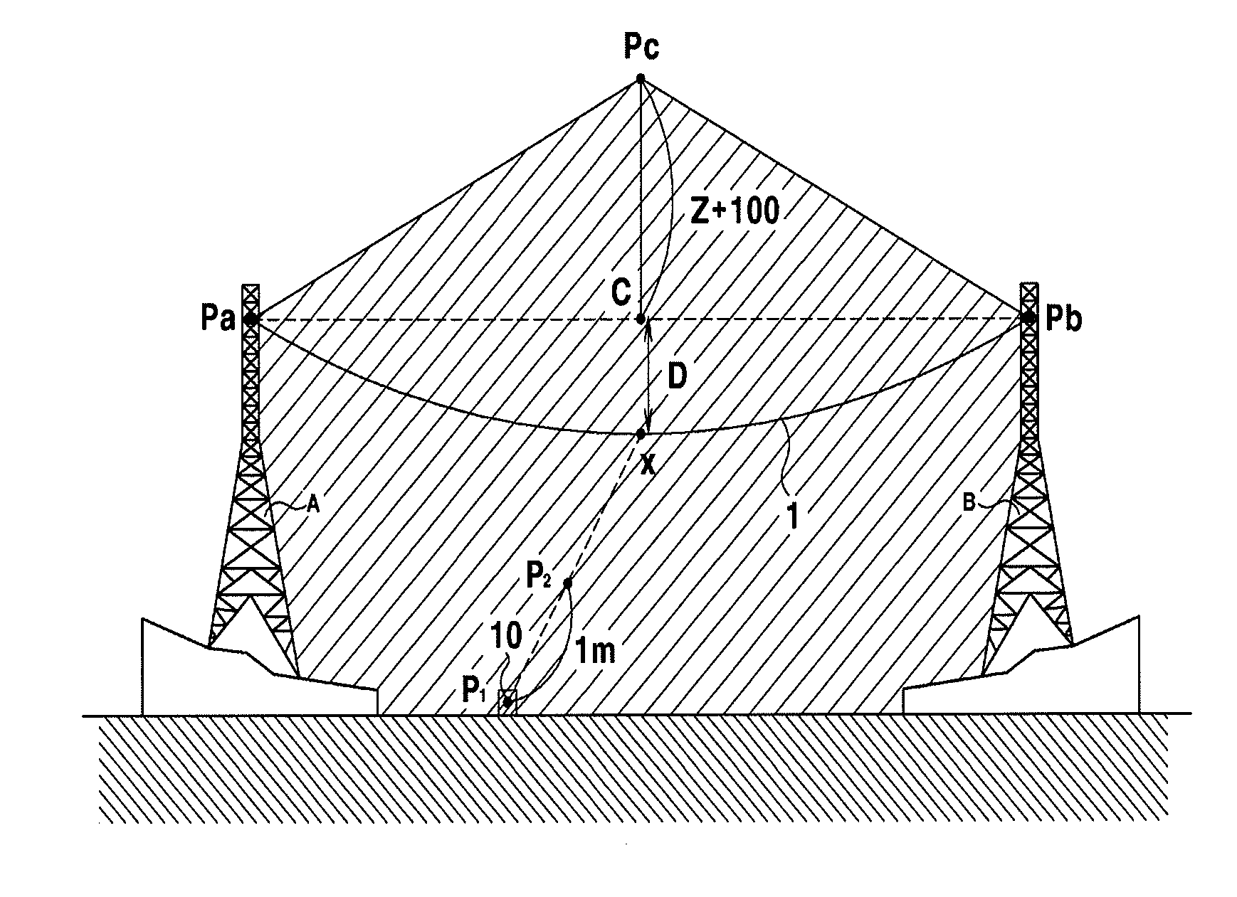
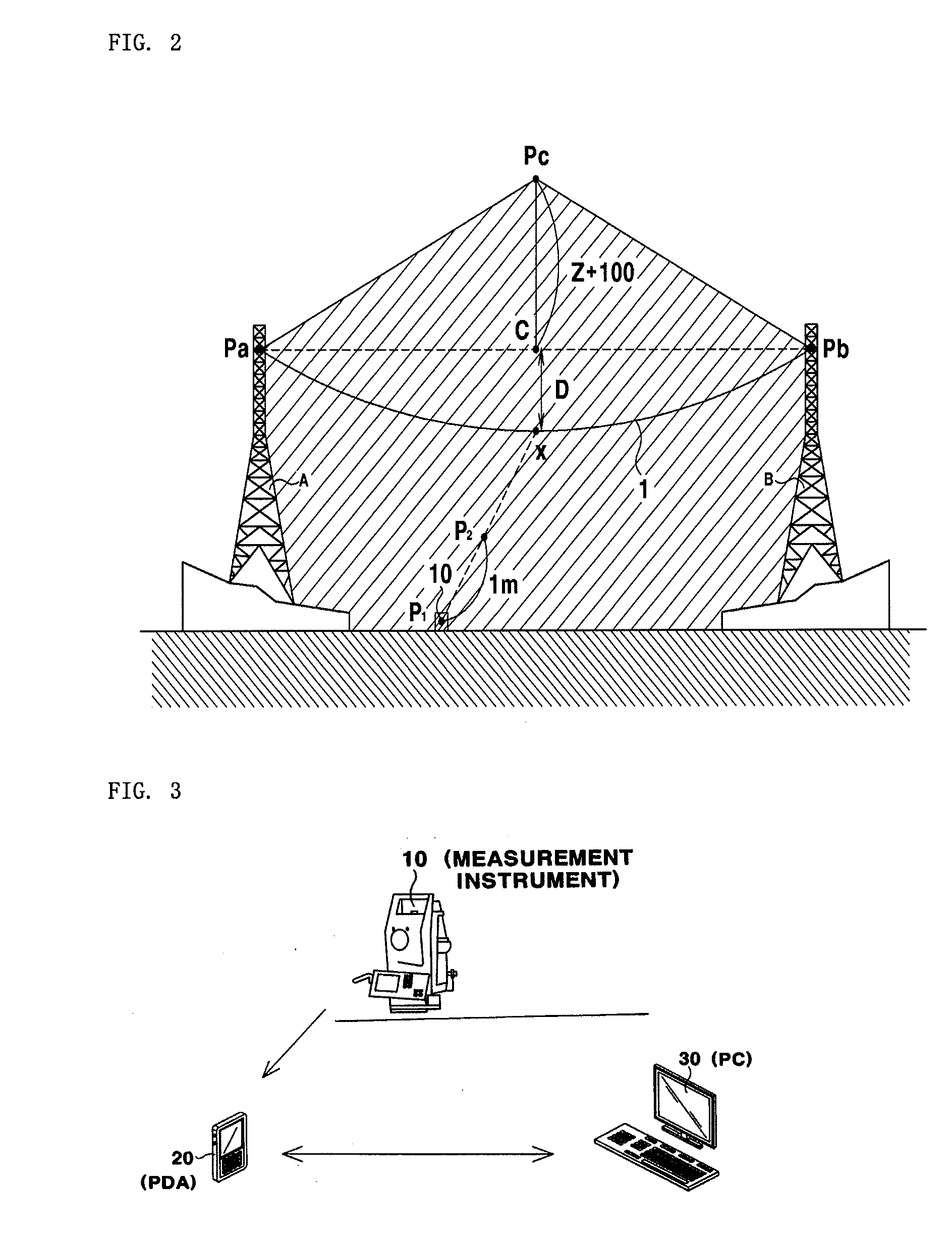
[0026]First, a dip measurement method according to the present invention will be described with reference to FIG. 2.[0027]A normal vector, an azimuth angle, and a perpendicular angle of a plane formed by a power line support point Pa of a steel tower A, a power line support point Pb of a steel tower B, and a point Pc obtained by adding an arbitrary number, for example 100, to a z-coordinate value of a center point C between the power line support point Pa and the power line support point Pb are defined as N, h, and v, respectively.[0028]When an arbitrary point, distant from a positional point P1 of a measurement instrument by 1 meter, of an imaginary line that links the positional point P1 and a power line dip point X is defined as P2,

hd=1.0*sin(v)

P2x=P1x÷hd*sin(h); (x-coordinate of P2)

P2y=P1y+hd*cos(h); (y-coordinate of P2)

P2z=P1z+1*cos(v); (z-coordinate...


PUM


Abstract

A power transmission line dip measurement method is disclosed. The dip measurement method includes installing a measurement instrument at a place where power line support points of steel towers can be seen from the ground, collimating the measurement instrument at the power line support point of one of the steel towers, transmitting a collimated value to a PDA in a wired or wireless manner, collimating the measurement instrument at the power line support point of the other steel tower, transmitting a collimated value to the PDA, calculating the collimated values to display a horizontal angle position of a dip base line, and adjusting an angle of the measurement instrument based on the horizontal angle displayed on a screen of the PDA by a worker, collimating the measurement instrument at a power line dip point as a dip base point, and displaying a dip value on the screen of the PDA.

Description

BACKGROUND OF THE INVENTION[0001]1. Field of the Invention[0002]The present invention relates to a power transmission line dip measurement method, and more particularly to a power transmission line dip measurement method that is capable of easily and accurately constructing a power cable based on a designed dip during the construction of the power line at power transmission steel towers and, in addition, of accurately measuring a dip of an already constructed power line.[0003]2. Description of the Related Art[0004]Generally, the shortest straight distance between a straight line linking power line support positions of two power transmission steel towers and a vertex of a power line is referred to as a power line dip D. The vertex is the lowest point of a curve formed by the power line when the power line is connected to the power line support positions of the power transmission steel towers.[0005]A conventional power line dip measurement method is an indirect type measurement method...

Claims


Application Information

Patent Timeline
Patent Type & Authority Applications(United States)
IPC IPC(8): G01B21/16G01B11/14G06F15/00
CPCH02G1/04H02G1/02
Inventor O, SEONG UNGSEO, CHUL WONSIM, BAEK SEOB
Owner KPS CO LTD
Why Eureka
Try Eureka