System and method for treating exhaust gases

a technology of exhaust gas and system, applied in the field of exhaust system, can solve the problems of increased emissions of nosub>x/sub>, limited capacity of ammonia storage element, and increased ammonia emissions of ammonia based systems

Active Publication Date: 2010-06-10
CATERPILLAR INC
View PDF11 Cites 10 Cited by
  • Summary
  • Abstract
  • Description
  • Claims
  • Application Information

AI Technical Summary

Problems solved by technology

If excess oxygen is present, the local mixture is lean, and the combustion usually results in the emission of increased NOx.
In meeting these regulations, engine manufacturers are challenged with designing engines that both meet stringent exhaust regulations as well as provide fuel-efficient power conversion.
However, some ammonia based systems may produce excess ammonia (for example, more ammonia than the system is capable of reacting and / or storing).
. . coupl[es] the storage tank to the exhaust system upstream of an ammonia storage element to reduce and direct any escaping ammonia toward the rear of the vehicle away from a refueling location.” However, the capacity of the ammonia storage element may be limited.

Method used


Image

  • System and method for treating exhaust gases
  • System and method for treating exhaust gases
  • System and method for treating exhaust gases

Examples


Embodiment Construction

[0017]Reducing the amount of ammonia that may exit an exhaust system as ammonia may be desirable in any exhaust system that uses ammonia to reduce emissions of NOx. Consequently, the systems and / or methods described herein may be used in an exhaust system that includes an ammonia salt, liquid ammonia, other ammonia source, or combinations thereof.

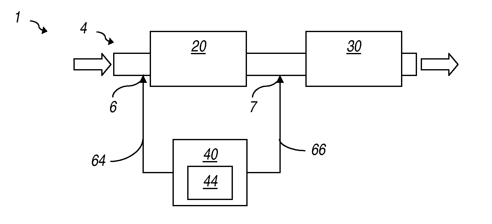
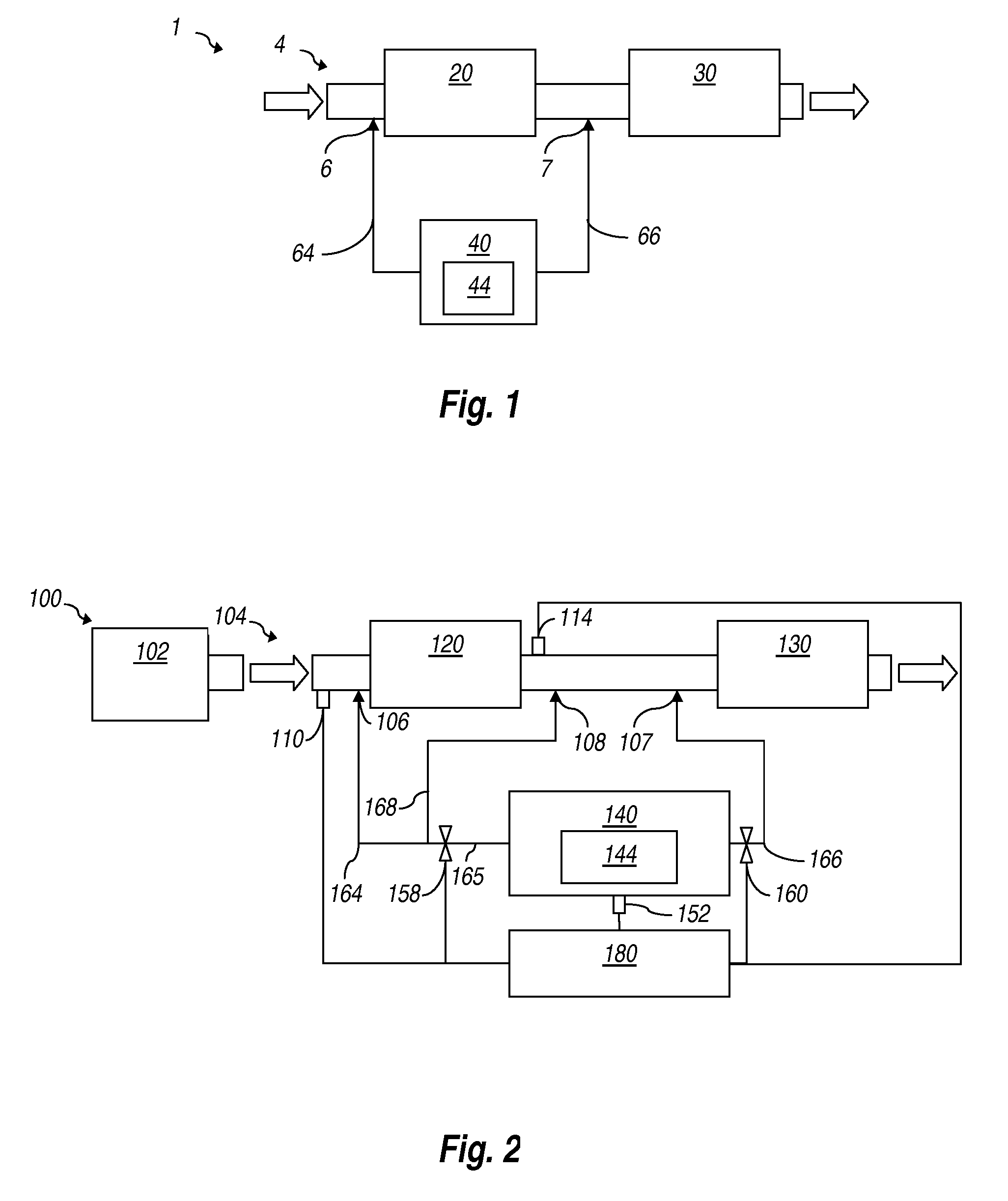
[0018]FIG. 1 is a diagrammatic illustration of an exhaust system 1 according to an example embodiment. The exhaust system 1 includes a conduit 4 that is in fluid communication with an ammonia-to-NOx catalyst 20 and an ammonia-SCR catalyst 30. A first inlet 6, with associated first fluid conduit 64, and a second inlet 7, with associated second fluid conduit 66, receive ammonia 44 from an ammonia source 40 and aid with delivering or directing ammonia toward conduit 4. As illustrated, the first inlet 6 may be located upstream of at least a portion of the ammonia-to-NOx catalyst 20 and the second inlet 7 may be located upstream of at least a po...


PUM

PropertyMeasurementUnit
temperatureaaaaaaaaaa

Abstract

Systems and methods for treating exhaust gases are described. The disclosed systems and/or methods for treating exhaust gases could be used with any power plant, engine, hydrocarbon burning system, other NOx producing system, or combinations thereof. A method (400) for treating exhaust gases is provided. The method (400) may include converting (402) a first quantity of ammonia (44) using an ammonia-SCR catalyst (30) to produce gaseous nitrogen and water and converting (404) a second quantity of ammonia using an ammonia-to-NOx catalyst (20) located upstream of at least a portion of the ammonia-SCR catalyst (30) to produce NOx.

Description

TECHNICAL FIELD [0001]This disclosure generally relates to exhaust systems and more particularly to a system and method for treating exhaust gases.BACKGROUND [0002]Power plants, such as some furnaces, internal and external combustion engines, or other hydrocarbon burning devices may emit pollutants such as carbon monoxides, nitrogen oxides (NOx, including NO and NO2), particulate matters, and sulfur oxides, to name a few. During the combustion process of these engines or fuel-burning plants, fuel ignites in the presence of oxygen. If excess oxygen is present, the local mixture is lean, and the combustion usually results in the emission of increased NOx. If excess fuel is present, the local mixture is rich, and the combustion will result in the emission of unburned hydrocarbon, soot, soluble organic fraction (SOF), and sulfates, generally termed particulate matter. Consequently, most engines emit a mixture of NOx and particulate matter.[0003]Emission of many of these pollutants is re...

Claims


Application Information

Patent Timeline
Patent Type & Authority Applications(United States)
IPC IPC(8): F01N3/035
CPCB01D53/9409F01N13/009B01D53/9495B01D2251/2062B01D2251/2067B01D2255/102B01D2258/012F01N3/106F01N3/208F01N2560/06F01N2560/08F01N2560/14F01N2610/02F01N2610/146F01N2900/1402F01N2900/1622F01N2900/1808Y02T10/24B01D53/9477Y02T10/12
Inventor DRISCOLL, JAMES JOSHUAFLINN, MICHAEL A.
Owner CATERPILLAR INC
Why Eureka
Try Eureka