Class-e amplifier and lighting ballast using the amplifier

a class-e amplifier and amplifier technology, applied in the direction of electric variable regulation, process and machine control, instruments, etc., can solve problems such as the risk of damage to the mos

Inactive Publication Date: 2010-06-10
GENERAL ELECTRIC CO
View PDF5 Cites 16 Cited by
  • Summary
  • Abstract
  • Description
  • Claims
  • Application Information

AI Technical Summary

Problems solved by technology

On the other hand, the class E amplifier generates substantial harmonic energy while induc

Method used


Image

  • Class-e amplifier and lighting ballast using the amplifier
  • Class-e amplifier and lighting ballast using the amplifier
  • Class-e amplifier and lighting ballast using the amplifier

Examples


Embodiment Construction

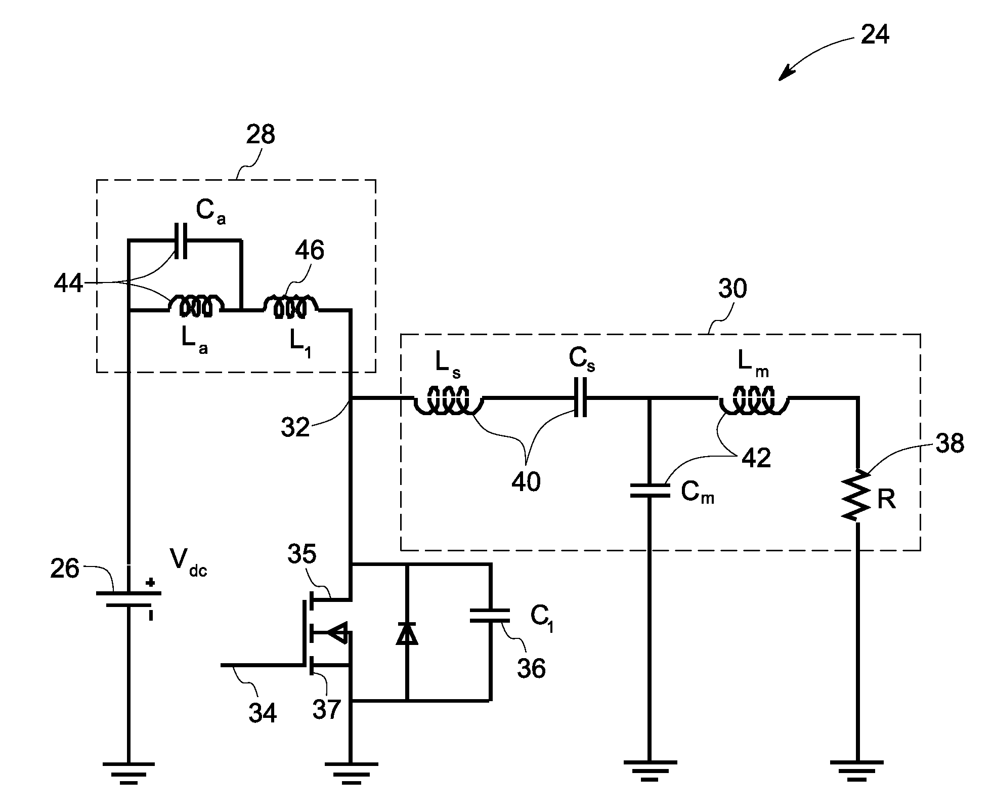
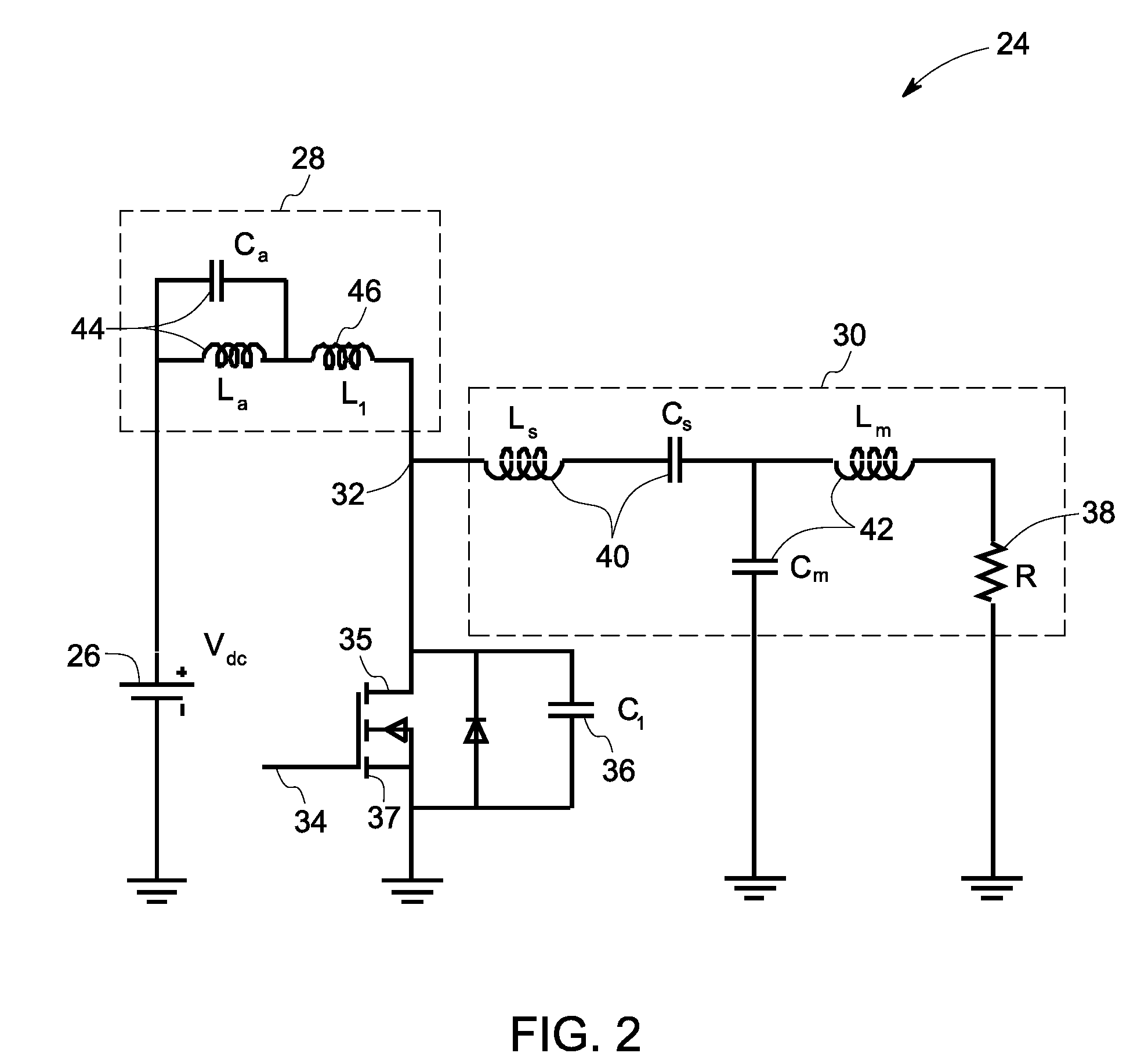
[0013]Embodiments disclosed herein relate to a Class-E amplifier which includes an input branch with one end connected to a power source and another end connected to an active switch and a load network. The input branch includes a parallel-LC-circuit with high impedance at harmonics of a determined order. Accordingly, such harmonics are prevented from affecting a voltage across the active switch. For purposes of simplicity of description, common elements across different embodiments share the same reference numbers.

[0014]FIG. 2 is an equivalent circuit of an exemplary Class-E amplifier 24 according to one embodiment of the invention. The Class-E amplifier 24 includes a power source 26 for driving a load network 30, an input branch 28 having one end connected to the power source 26 and another end or a drain point 32 connected to the load network 30, and an active switch 34 also connected to the drain point 32 of the input branch 28. In one embodiment, the power source 26 is a direct...


PUM


Abstract

An amplifier comprises a power source, a load network comprising a load and a resonance circuit, an input branch having a first end electrically coupled to the power source and a second end electrically coupled to the load network, and an active switch having one terminal electrically coupled to the second end of the input branch. The input branch including at least one parallel-LC-circuit configured to provide an infinitely large impedance at harmonics of a determined order.

Description

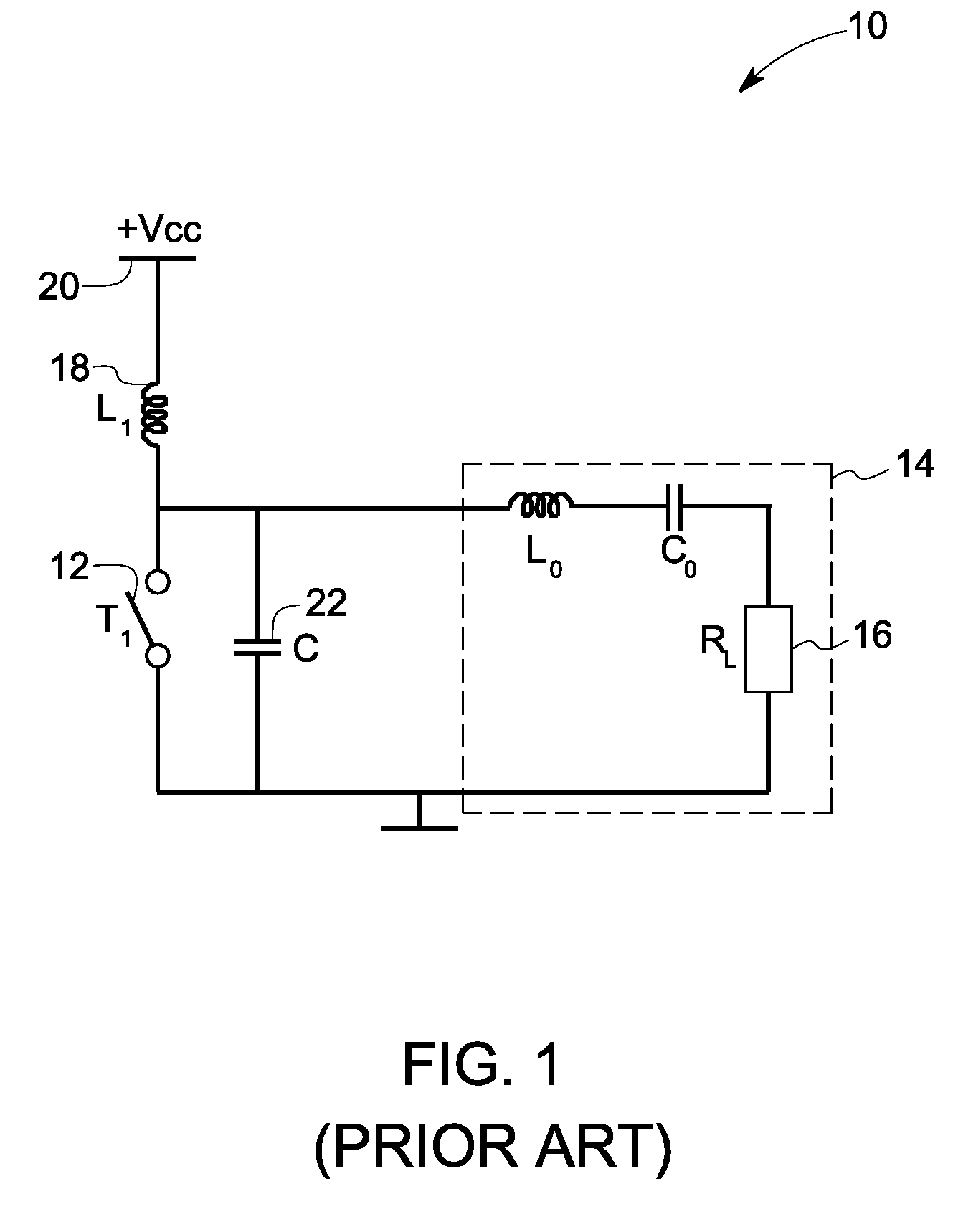
BACKGROUND[0001]Embodiments of the invention are generally related to the field of electronic amplifiers and electronic devices using the amplifiers, and more particularly, to a Class-E amplifier and a lighting ballast using the Class-E amplifier.[0002]Class-E amplifiers are highly efficient switching power amplifiers, operating at high frequencies. Referring to FIG. 1, a typical class-E amplifier 10 includes a transistor 12, such as a metal-oxide-silicon field-effect transisor (MOSFET), connected via a serial-LC-circuit 14 to a load 16, and connected via a large inductor 18 to a power source 20. Capacitor 22 represents parasitic capacitance of the transistor 12 or may include an additional capacitor. At an ON stage of the MOSFET, the voltage across the MOSFET is close to zero, and when the MOSFET is OFF, the current through the MOSFET is close to zero. Together with capacitor 22, the serial-LC-circuit 14 shapes the voltage and current waveforms to prevent simultaneous high voltage ...

Claims


Application Information

Patent Timeline
IPC IPC(8): H05B41/36H03F3/16
CPCH03F3/2176Y02B20/22H05B41/2806Y02B20/00
Inventor ZHANG, YINGQILI, JIANWULIU, YUNFENGLI, WUHUA
Owner GENERAL ELECTRIC CO
Why Eureka
Try Eureka