Dipole array with reflector and integrated electronics

a technology of reflectors and dipole arrays, applied in the direction of resonant antennas, independent non-interacting antenna combinations, instruments, etc., can solve the problems of inefficient and narrow band design of electronic enclosures, limited bandwidth, and high transmit power requirements, so as to reduce the size and complexity of antennas and improve the signal strength received

Inactive Publication Date: 2010-06-10
SENSIS CORPORATION
View PDF17 Cites 30 Cited by
  • Summary
  • Abstract
  • Description
  • Claims
  • Application Information

AI Technical Summary

Benefits of technology

[0008]The system and method of the present invention improves the signal strength received at the integrated electronics and reduces the size and complexi...

Problems solved by technology

Many current designs that incorporate antennas into electronic enclosures are inefficient and narrow band.
These devices require higher transmit power and suffer from limited bandwidth as well a...

Method used


Image

  • Dipole array with reflector and integrated electronics
  • Dipole array with reflector and integrated electronics
  • Dipole array with reflector and integrated electronics

Examples


Embodiment Construction

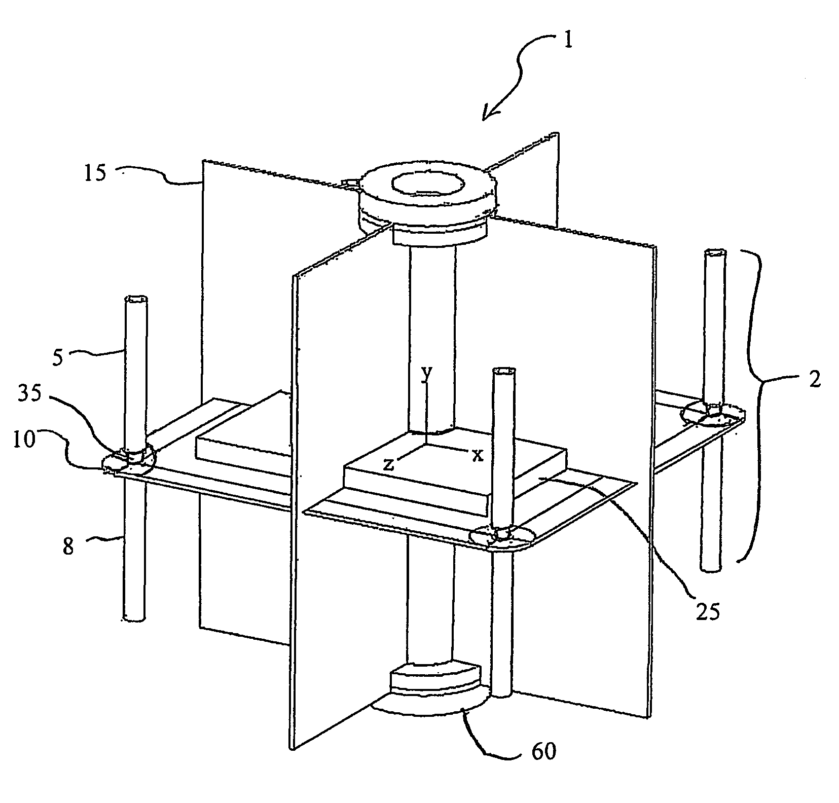
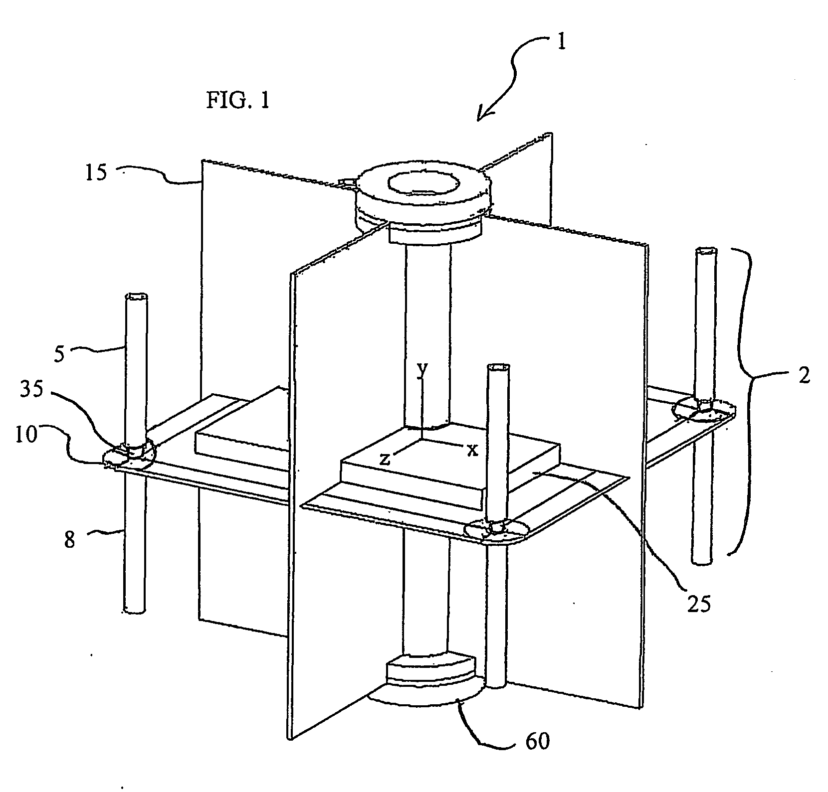
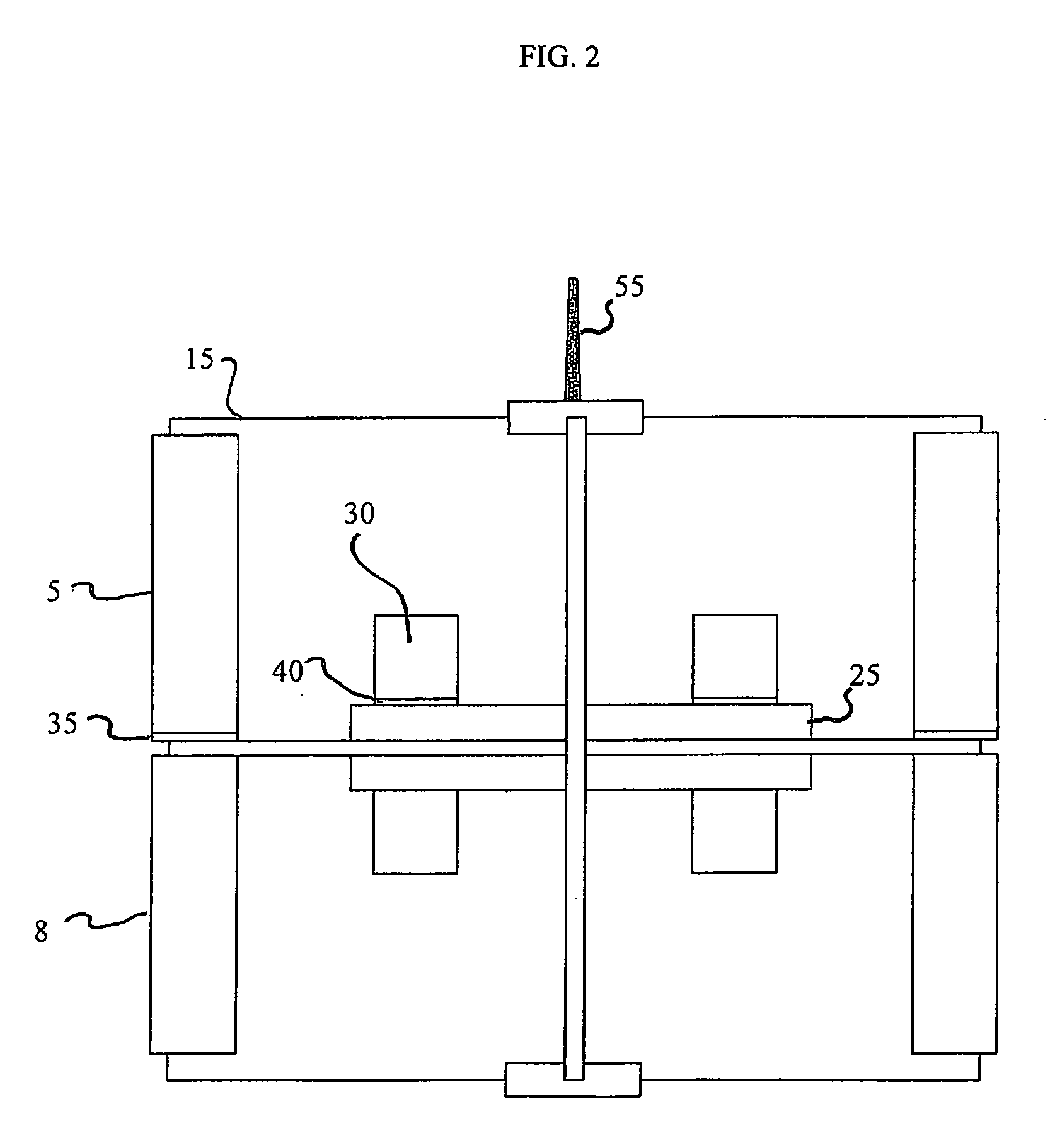
[0052]The ½ wave dipole is a classic antenna element with the signal generator, such as a transceiver, located at the mid-point having the bottom half of the wire common to the grounded side and the top half connected to the source. The radius of the active dipole element used in the dipole antenna will determine the bandwidth of the signal to be transmitted or received. A reflector added in parallel to the element increases the antenna gain in the direction opposite the reflector in relation to the element. Within the symmetry of the center of the element and the reflector, there is a plane common to the ground point of the generator. The present invention uses this plane to incorporate the electronic circuitry necessary for the purpose of receiving, transmitting, decoding, and any other function which utilizes these signals and other system requirements. Also, the reflector is used to incorporate electronic circuitry. Also, multiple elements and reflectors are placed to create a c...


PUM


Abstract

A dipole antenna array comprising a ground plane, at least one dipole antenna including an active antenna element and a grounded antenna element, at least one reflector and integrated electronics, wherein the active antenna element is isolated from the ground plane and extends substantially perpendicular to the ground plane and the grounded antenna element extends in a direction substantially opposite to the active antenna element, the ground plane is contained within the area bounded by the reflector; the integrated electronics include at least one of a signal down converter and a signal up-converter, and at least some of the integrated electronics are contained in a space defined by at least one of a portion of the ground plane and a portion of the reflector.

Description

CROSS-REFERENCE TO RELATED APPLICATIONS[0001]This application claims the benefit of U.S. Provisional Patent Application No. 61 / 121,296, filed Dec. 10, 2008, the entirety of which is incorporated herein by reference.FIELD OF INVENTION[0002]The present invention is directed to systems and methods for increasing modularity and portability, improving quality of received and transmitted signals, incorporating functions necessary for a complete system in a compact design, and requiring either narrow band or wide band wireless applications. The present invention is directed to applications for direction finding of wireless signals, systems designed for decoding overlapping signals in time, and systems requiring methods for mitigating multipath signals. The present invention also provides functions for systems requiring repeaters or systems where nodes are utilized to economically extend existing wireless systems with minimal cost of infrastructure.BACKGROUND OF THE INVENTION[0003]Antennas ...

Claims


Application Information

Patent Timeline
IPC IPC(8): G01S5/02H01Q19/10H01Q21/00H01Q9/16H01Q5/378H01Q5/40H01Q5/48H01Q5/49
CPCH01Q1/246H01Q9/18H01Q9/20H01Q19/106H01Q5/49H01Q21/28H01Q5/378H01Q5/40H01Q5/48H01Q19/108
Inventor MCMAHON, STEPHEN E.
Owner SENSIS CORPORATION
Why Eureka
Try Eureka