View Projection Matrix Based High Performance Low Latency Display Pipeline

Active Publication Date: 2010-06-10
SEIKO EPSON CORP
View PDF7 Cites 80 Cited by
  • Summary
  • Abstract
  • Description
  • Claims
  • Application Information

AI Technical Summary

Benefits of technology

[0034]The above objects are met in a system that simplifies the generation of transport matrix T, simplifies the implementation of light transport coefficients i

Problems solved by technology

Thus, a key problem that builders of projector-camera systems and devices need to solve is the determination of the internal imaging parameters of each device (i.e., intrinsic parameters) and the determination of the geometric relationship between all projectors and cameras in the system (i.e., extrinsic parameters).
Even after a system has been substantially calibrated, however, the issue of adjusting a projection to compensate for distortions in a projected image is not straightforward.
Identifying and compensating for projection distortion can be a very computationally intensive operation, which has traditionally greatly limited its application to non-specialized fields.
However, since all camera calibration techniques require that the camera requiring calibration (i.e., the imaging device being calibrated) capture a number of images, it would appear that camera calibration techniques cannot readily be applied to projectors since projectors cannot capture images.
While this bootstrapping technique is a tested-and-proven calibration method for projector-camera systems, it is not applicable to the calibration of self-contained projector-camera devices, since it requires the use of pre-calibrated; strategically located, external stereo camera pairs, and thus requires much o

Method used


Image

  • View Projection Matrix Based High Performance Low Latency Display Pipeline
  • View Projection Matrix Based High Performance Low Latency Display Pipeline
  • View Projection Matrix Based High Performance Low Latency Display Pipeline

Examples


Example

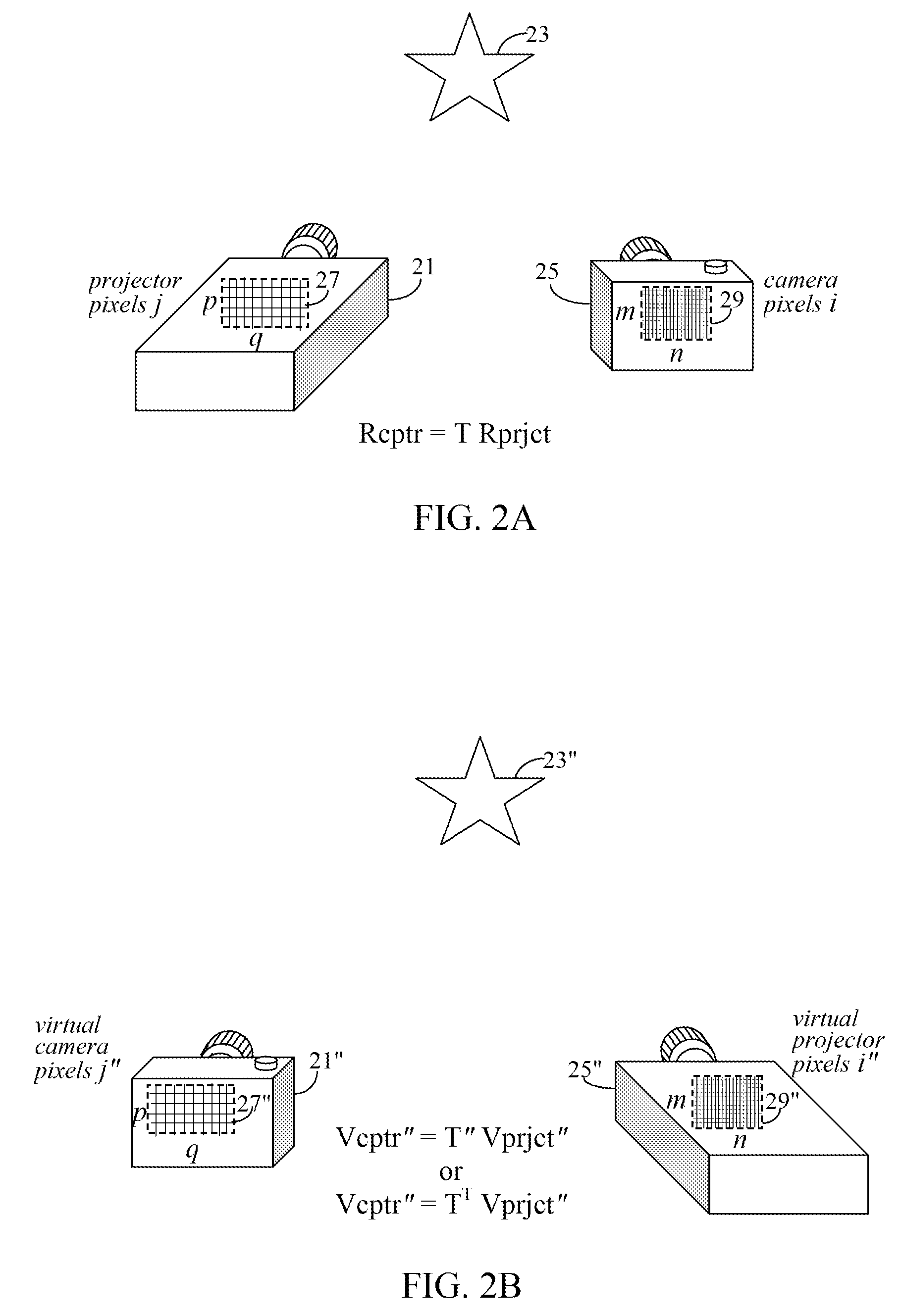
[0134]In the present first embodiment, it is assumed that the pixel resolution of real camera 25 is at least four times greater than that of real projector 21 and that the projection scene is devoid of any light diffusing material, such that the requirements for the ideal light ray distribution condition are met. Nonetheless, alternative embodiments for more general situations where the resolution of real camera 25 is not restricted to be greater than real projector 21, or where the light path between real projector 21 and real camera 25 is not limited to be devoid of light diffusing material are provided below.

[0135]A first pictorial representation of the present assumptions and vector generation method is shown in FIGS. 3A to 3C. With reference to FIG. 3A, an illustrative example of the present invention shows real projector pixel array 27 having a pixel resolution smaller than that of real camera sensor pixel array 29. For ease of discussion, projector pixel array 27 is illustrat...


PUM


Abstract

A projection system uses a transformation matrix to transform a projection image p in such a manner so as to compensate for surface irregularities on a projection surface. The transformation matrix makes use of properties of light transport relating a projector to a camera. A display pipeline of user-supplied image modification processing modules are reduced by first representing the processing modules as multiple, individual matrix operations. All the matrix operations are then combined with, i.e., multiplied to, the transformation matrix to create a modified transformation matrix. The created transformation matrix is then used in place of the original transformation matrix to simultaneously achieve both image transformation and any pre and post image processing defined by the image modification processing modules.

Description

BACKGROUND[0001]1. Field of Invention[0002]The present invention is related to a method of implementing display pipelines with reduce display latency. The present invention is further related to methods of reducing display latency in a display system designed to compensate for irregular surfaces and lighting in a projection scene.[0003]2. Description of the Related Art[0004]When projectors and cameras are combined, hybrid devices and systems that are capable of both projecting and capturing light are born. This emerging class of imaging devices and systems are known in the research community as projector-camera systems. Typically, images captured by one or more cameras, are used to estimate attributes about display environments, such as the geometric shapes of projection surfaces. The projectors in these projector-camera systems then adapt their projected images so as to compensate for shape irregularities in the projection surfaces to improve the resultant imagery. In other words, ...

Claims


Application Information

Patent Timeline
IPC IPC(8): H04N5/228H04N9/31
CPCH04N9/3182H04N17/002H04N9/3194H04N9/3185H04N9/3147
Inventor TAN, KAR-HANSONEHARA, TOMIO
Owner SEIKO EPSON CORP
Why Eureka
Try Eureka