
Method for producing color filter, color filter, liquid crystal display device and producing apparatus

Active Publication Date: 2010-06-10
ULVAC INC
View PDF3 Cites 1 Cited by
  • Summary
  • Abstract
  • Description
  • Claims
  • Application Information

AI Technical Summary

Benefits of technology

[0042]Since the first and second targets are disposed inside the same vacuum chamber, it is easy to reduce the size of the producing apparatus, and the producing cost of the producing apparatus is low. Since the first and second targets are sputtered in the same film forming atmosphere, a step of forming the inorganic protection film and a step of forming the transparent electrode are continuously performed, so that the time for producing the color filter is shortened. The inorganic protection film is not exfoliated from the transparent electrode or the resin layer. The inorganic protection layer has high insulation.

Problems solved by technology

However, since the SiO2 film largely differs in linear expansion coefficient from the transparent electrode (such as, for example, ITO), there was a problem that the transparent electrode was likely to be exfoliated from the SiO2 film.
However, when the SiO2 target is used, an RF (radio frequency) power source is employed because the discharging of electricity is not stabilized in such cases as when a DC (direct current) power source or an AC (alternate current) power source is used.
For this reason, it was difficult to form a SiO2 film and a transparent electrode film (ITO) in the same chamber, thereby resulting in the production of apparatuses that are large.
Further, in using the reactive sputtering for the formation of the SiO2 film, there have been the problems due to the occurrence of arcing, and of low film forming speed.
Moreover, when the RF power source is used, the cost of the apparatus tend to increase due to the added costs of the power source and treatment for surface waves.

Method used


Image

  • Method for producing color filter, color filter, liquid crystal display device and producing apparatus
  • Method for producing color filter, color filter, liquid crystal display device and producing apparatus
  • Method for producing color filter, color filter, liquid crystal display device and producing apparatus

Examples


example 1

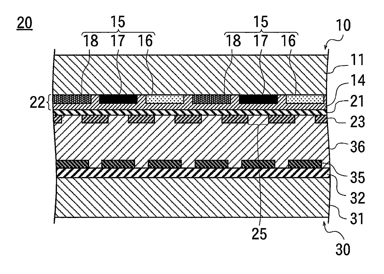
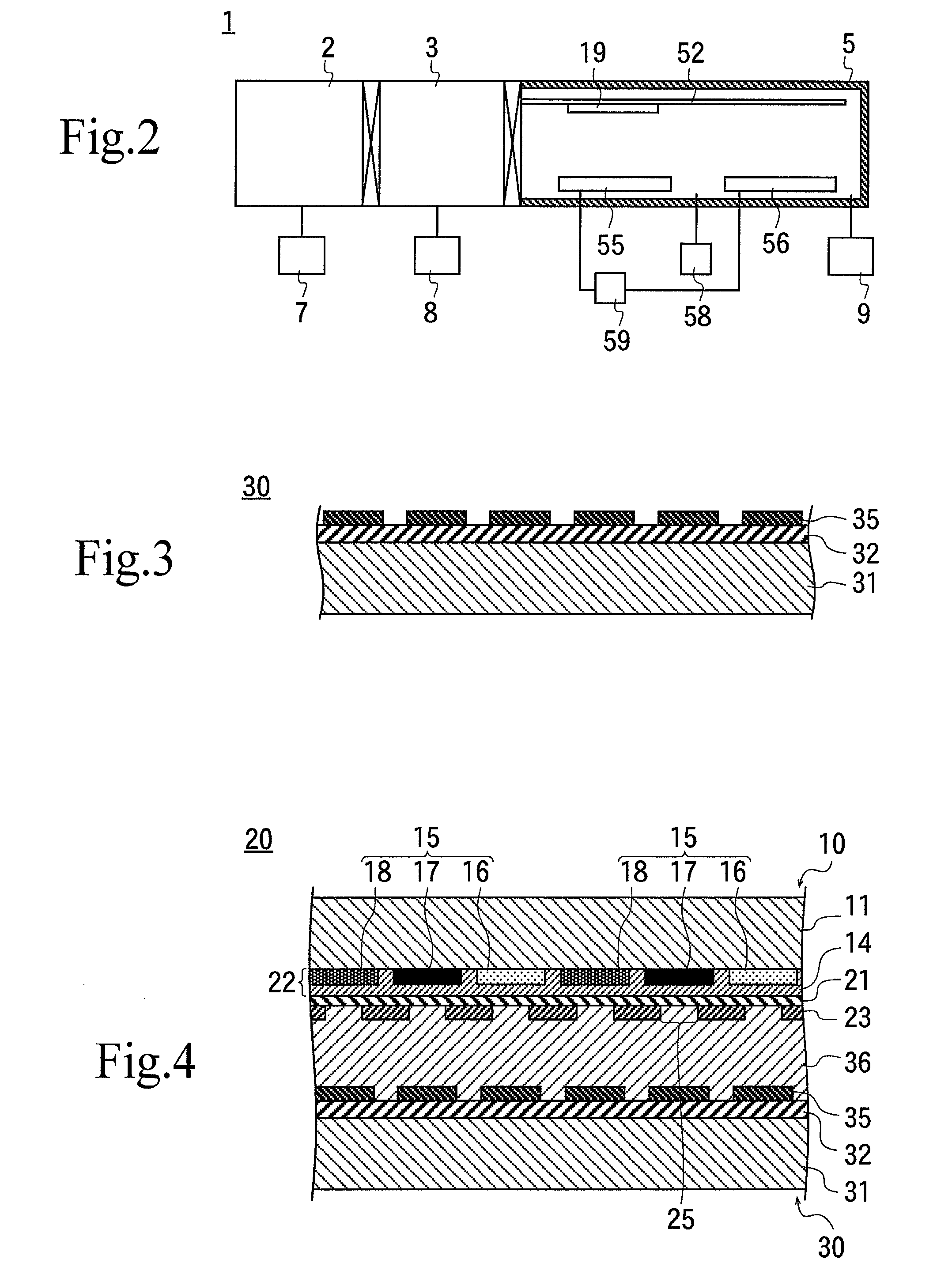
[0118]A first target 55 composed mainly of SnO2 and with Sb2O3 added as an impurity and a second target 56 composed mainly of In2O3 and with SnO2 added as an additive were placed inside the film forming chamber 5 in the aforementioned FIG. 2; and an object to be processed 19 was carried into the film forming chamber 5 without being heated in the heating chamber 3, while the heating chamber 3 and the film forming chamber 5 were kept in a high vacuum atmosphere.

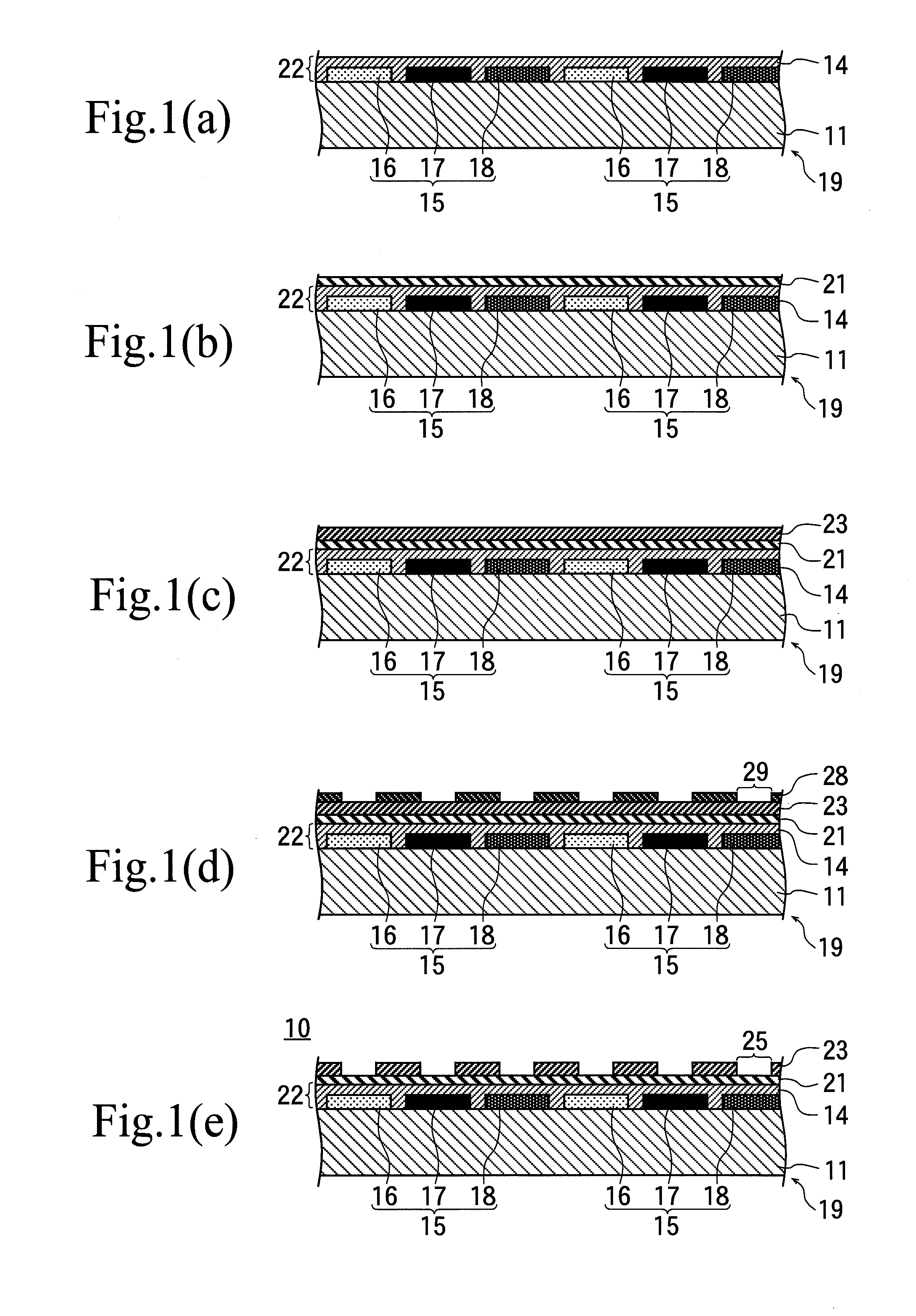
[0119]While an Ar gas and an oxygen gas were being fed into the film forming chamber 5, a direct current voltage was applied to the first and second targets 55, 56, an inorganic protection film 21 (film thickness of 50 Å) composed mainly of SnO2 and a film of a transparent electrode 23 composed mainly of ITO (film thickness of 1500 Å) were formed on a surface of the resin layer 22 under a non-heating condition by the steps of the aforementioned FIGS. 1(b) and (c). This was taken as an evaluation substrate in Example 1.

example 2

[0120]An evaluation substrate produced under the same condition in Example 1 was annealed by heating in air for one hour, and was taken as an evaluation substrate in Example 2.

example 3

[0121]An evaluation substrate in Example 3 was produced under the same condition as in the above-discussed Example 1, except that an object 19 to be processed was heated at 250° C. with the heaters provided in the heating chamber 3 and the film forming chamber 5 and an inorganic protection film 21 and a film of a transparent electrode 23 were formed.


PUM

PropertyMeasurementUnit
Temperatureaaaaaaaaaa
Partial pressureaaaaaaaaaa
Pressureaaaaaaaaaa

Abstract

Exfoliation of an etching stopper is prevented. A color filter of the present invention includes an inorganic protection film (etching stopper) composed mainly of SnO2. Since the inorganic protection film as such not only has a high specific resistance but also has a linear expansion coefficient close to the linear expansion coefficient of a transparent electrode, the inorganic protection film is not exfoliated from the transparent electrode or the resin layer even if an object to be processed is heated. Since the inorganic protection film and the transparent electrode can be formed in the same film forming chamber, the time required to produce the color filter can be shortened as compared to in the conventional technique.

Description

[0001]This application is a continuation of International Application No. PCT / JP2008 / 064802, filed on Aug. 20, 2008, which claims priority to Japan Patent Application No. 2007-215996, filed on Aug. 22, 2007. The contents of the prior applications are herein incorporated by reference in their entireties.BACKGROUND OF THE INVENTION[0002]1. Field of the Invention[0003]The present invention generally relates to a technology for producing a liquid crystal display device.[0004]2. Description of the Background Art[0005]There are a TN (Twisted Nematic) system, a VA (Vertical Alignment) system or the like, for the liquid crystal display devices, and a PVA (Patterned Vertical Alignment) system having a wider view angle, a higher contrast, and so forth have recently attracted attention.[0006]The PVA system liquid crystal display device possesses a color filter having a colored resin layer and a transparent electrode (counter electrode) laminated on a transparent substrate and a pixel substrate...

Claims


Application Information

Patent Timeline
IPC IPC(8): G02F1/1335G02B5/22B29D11/00C23C14/34
CPCG02B5/201G02F2202/28G02F1/134336G02F1/133516
Inventor TAKAHASHI, HIROHISASUGIURA, ISAOOHTA, ATSUSHIISHIBASHI, SATORU
Owner ULVAC INC
Learn More