Check patentability & draft patents in minutes with Patsnap Eureka AI!

Physical quantity measuring apparatus utilizing optical frequency domain reflectometry, and method for simultaneous measurement of temperature and strain using the apparatus

Active Publication Date: 2010-06-10
THE FUJIKURA CABLE WORKS LTD
View PDF5 Cites 36 Cited by
  • Summary
  • Abstract
  • Description
  • Claims
  • Application Information

AI Technical Summary

Benefits of technology

[0032]According to the physical quantity measuring apparatus utilizing optical frequency domain reflectometry described in (1), since the measuring apparatus includes a FBG sensor arranged at the core of a polarization-maintaining fiber, and an incidence part for making measuring light incident to two orthogonal polarization axes of the polarization-maintaining fiber where the sensor is provided, the temperature and strain of the sensor can be measured simultaneously. Further, since the measuring apparatus includes the optical path-length adjuster for maintaining a constant (same) optical path-length of Bragg reflected light from the two orthogonal polarization axes of the sensor, the position of the sensor can be identified accurately, and physical quantities can be measured with high spatial resolution.
[0033]According to the method for simultaneous measurement of temperature and strain described in (8), which uses the physical quantity measuring apparatus utilizing optical frequency domain reflectometry described in any one of (1) to (7), strain and temperature from one FBG sensor can be measured simultaneously. Moreover, temperature distribution and strain distribution along the long direction of the FBG sensor can also be measured simultaneously.

Problems solved by technology

A general problem of optical fiber sensor systems includes that, when there is change in a plurality of physical quantities such as temperature and strain, it is not possible to independently identify and measure amount of these changes.

Method used


Image

  • Physical quantity measuring apparatus utilizing optical frequency domain reflectometry, and method for simultaneous measurement of temperature and strain using the apparatus
  • Physical quantity measuring apparatus utilizing optical frequency domain reflectometry, and method for simultaneous measurement of temperature and strain using the apparatus
  • Physical quantity measuring apparatus utilizing optical frequency domain reflectometry, and method for simultaneous measurement of temperature and strain using the apparatus

Examples


first embodiment

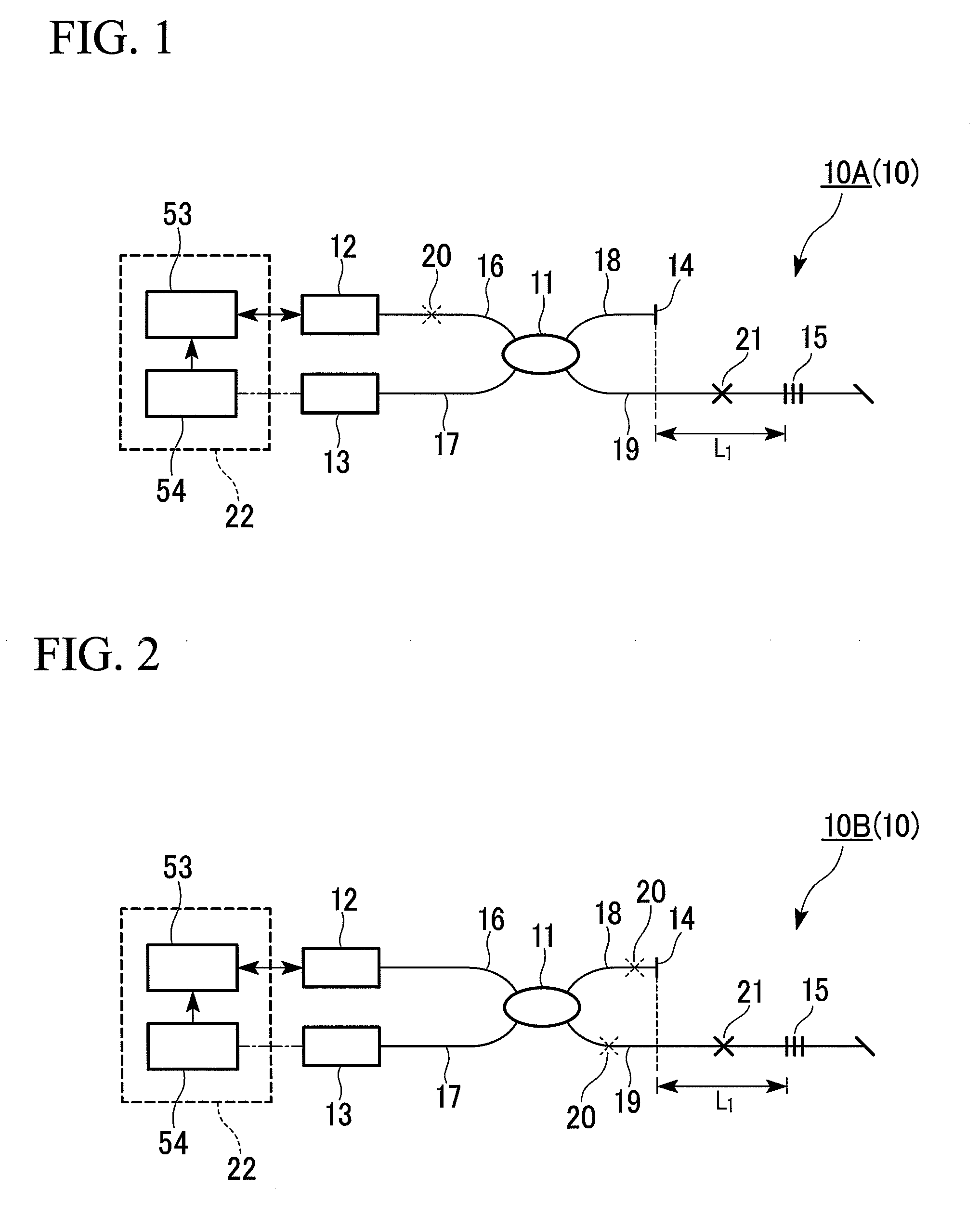
[0069]FIG. 1 is a schematic configuration view showing a first embodiment of a physical quantity measuring apparatus utilizing optical frequency domain reflectometry (hereinafter abbreviated as ‘OFDR’) of the invention.

[0070]A physical quantity measuring apparatus utilizing OFDR 10A (10) of this embodiment broadly includes a tunable laser 12 that emits measuring light; a first polarization-maintaining fiber 16 with one end thereof connected with the tunable laser 12; a polarization-maintaining coupler 11 connected with another end of the first polarization-maintaining fiber 16; a second polarization-maintaining fiber 18 with one end thereof connected with the polarization-maintaining coupler 11 and another end being a referential reflecting end 14; a third polarization-maintaining fiber 19 with one end thereof connected with the polarization-maintaining coupler 11; a sensor 15 consists of a fiber Bragg grating formed at the core of the third polarization-maintaining fiber 19; a four...

second embodiment

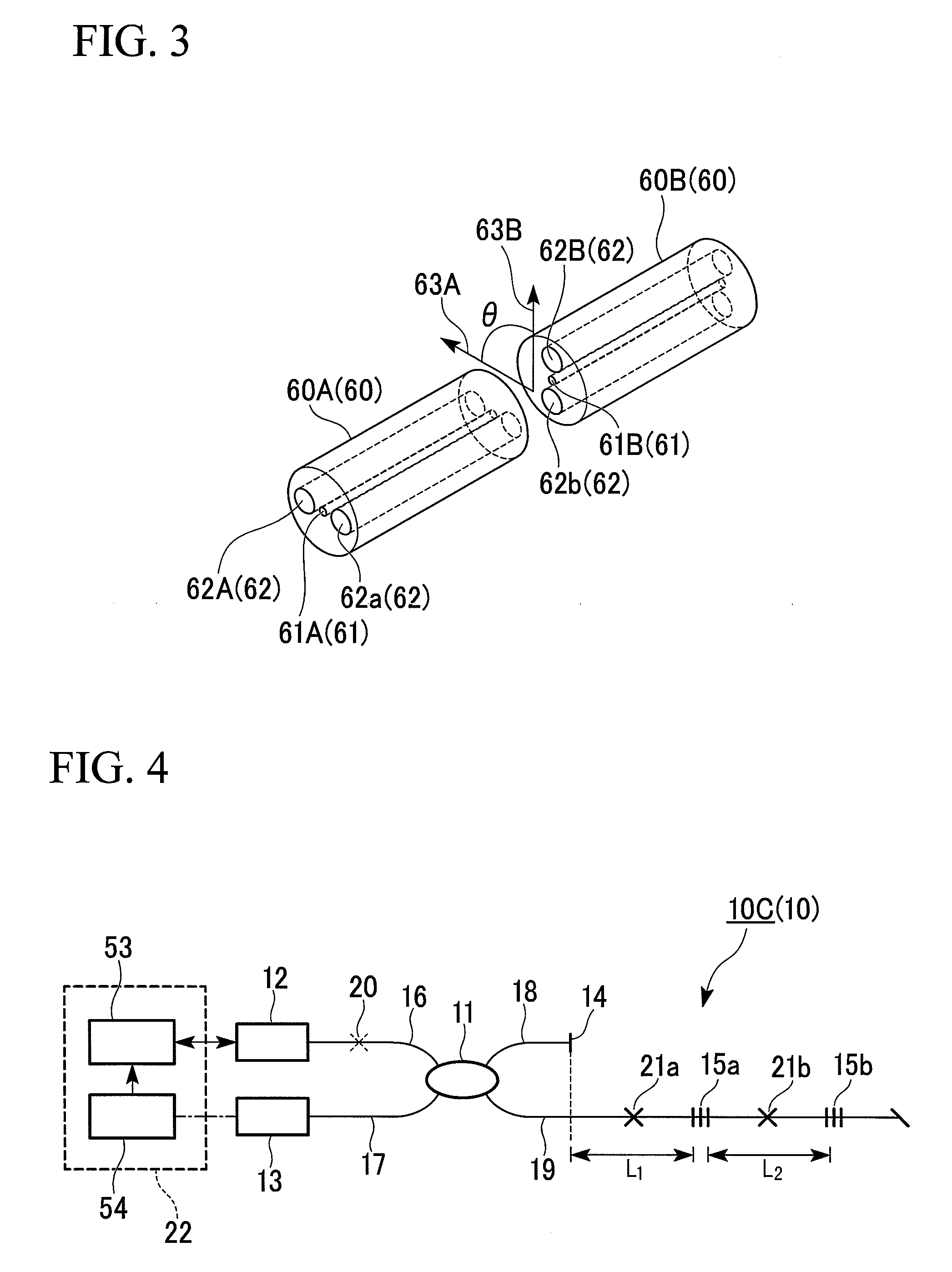
[0104]FIG. 4 is a schematic configuration view showing a second embodiment of the physical quantity measuring apparatus utilizing OFDR of the invention. A physical quantity measuring apparatus utilizing OFDR 10C (10) of this embodiment differs from the first embodiment in that a plurality of sensors 15 (in FIG. 4, two sensors 15a and 15b) are arranged on the third PM fiber 19.

[0105]The physical quantity measuring apparatus utilizing OFDR 10C of this embodiment further includes a second optical path-length adjuster 21b (21), provided midway in the fiber length between adjacent sensors (first sensor 15a and second sensor 15b). Therefore, optical path-lengths of Bragg reflected lights from two orthogonal polarization axes at the first sensor 15a and at the second sensor 15b can be made constant respectively. That is, when an interference signal between Bragg reflected lights from the first sensor 15a and the second sensor 15b, and reflected light from the referential reflecting end, is...

third embodiment

[0107]In the physical quantity measuring apparatus utilizing OFDR 10 according to the first and second embodiments described above, the third PM fiber 19 where the sensors 15 are arranged is preferably consists of a PM fiber with a large difference in the effective refractive indices of the two orthogonal polarization axes (birefringence).

[0108]This increases the difference in sensitivity to temperature and strain in the two orthogonal polarization axes, and enables temperature and strain to be simultaneously measured with high accuracy. More specifically, it is preferable that the difference in the effective refractive indices of the two orthogonal polarization axes is not less than 4.4×10⁻⁴. By satisfying this value, as shown by the results of examples described below, the shift characteristics difference of Bragg wavelength to sensor temperature change can be made greater than −5.0×10⁻⁴ nm / ° C. As a result, remarkably high accuracy measurements of temperature and strain can be ob...


PUM


Abstract

A physical quantity measuring apparatus utilizing optical frequency domain reflectometry of the invention includes a tunable laser; a first polarization-maintaining fiber; a polarization-maintaining coupler; a second polarization-maintaining fiber; a third polarization-maintaining fiber; a sensor consists of fiber Bragg gratings formed at a core of the third polarization-maintaining fiber; a fourth polarization-maintaining fiber; a photodiode detects Bragg reflected light from the sensor and reference light from the referential reflecting end; a controller detects a modulation of an interference intensity between the Bragg reflected light and the reference light, based on an intensity change of multiplexed light of the Bragg reflected light and the reference light; an incidence part inputs the measuring light; and an optical path-length adjuster arranged on the third polarization-maintaining fiber; the incidence part provided on the first polarization-maintaining fiber, or on both the second and third polarization-maintaining fibers.

Description

[0001]This is a Continuation Application of International Patent Application No. PCT / JP2009 / 053899, filed on Mar. 2, 2009. Priority is claimed on Japanese Patent Application No. 2008-51343, filed Feb. 29, 2008, and Japanese Patent Application No. 2008-239368, filed Sep. 18, 2008, the contents of which are incorporated herein by reference.TECHNICAL FIELD[0002]The present invention relates to a physical quantity measuring apparatus utilizing optical frequency domain reflectometry (OFDR), and to a method for simultaneous measurement of temperature and strain using the physical quantity measuring apparatus. In the physical quantity measuring apparatus utilizing OFDR, one or a plurality of fiber Bragg grating (FBG) sensors are arranged on a (one) polarization-maintaining (PM) fiber, and the position of the FBG sensor and physical quantities such as strain or temperature of the FBG sensor are measured.BACKGROUND ART[0003]A sensor that measures physical quantities such as temperature and s...

Claims


Application Information

Patent Timeline
IPC IPC(8): G01B11/16G01B9/02G01K11/32G02B6/00
CPCG01B11/18G01L1/246G01K11/3206G01D5/35303G01D5/35316G01D5/35354G01D5/3538G01D5/35393
Inventor OMICHI, KOJISAKAMOTO, AKIRAHIRAFUNE, SHUNICHIROU
Owner THE FUJIKURA CABLE WORKS LTD
Features
  • R&D
  • Intellectual Property
  • Life Sciences
  • Materials
  • Tech Scout
  • Unparalleled Data Quality
  • Higher Quality Content
  • 60% Fewer Hallucinations
Learn More