Divided-pulse amplification of short pulses

a technology of amplification and short pulses, applied in the field of short pulse amplification techniques, can solve the problems of affecting the amplification effect of chirped pulses, affecting the amplification effect of short pulses, and reaching the limit of chirped pulse amplification, so as to improve the amplification effect, and reduce the magnitude and energy

Active Publication Date: 2010-06-10
CORNELL UNIVERSITY
View PDF4 Cites 29 Cited by
  • Summary
  • Abstract
  • Description
  • Claims
  • Application Information

AI Technical Summary

Benefits of technology

[0008]The present invention is directed to a short-pulse amplification technique which produces improved performance over known CPA techniques, along with ease of implementation, in some situations. In this technique, referred to as divided-pulse amplification (DPA), a pulse to be amplified is divided into a plurality of smaller copies of itself. The pulses are approximately equally-spaced temporally in a sequence and have the same shape as the original pulse, but are of lower magnitude and energy. The sequence of pulses is amplified and then the pulses in the sequence are recombined coherently to produce a final large energy pulse, which is an amplified version of the original pulse. This arrangement reduces or avoids the nonlinear effects associated with other short-pulse amplification techniques.

Problems solved by technology

Amplification of the pulses with high fidelity is crucial, but nonlinear phase shifts accumulated by an intense pulse generally distort its spectral and temporal profiles.
However, the limits of chirped-pulse amplification are reached by many sources of picosecond and femtosecond pulses.
Many existing CPA systems are operated close to the limit ΦNL˜1, owing to limitations on the stretching ratio.

Method used


Image

  • Divided-pulse amplification of short pulses
  • Divided-pulse amplification of short pulses
  • Divided-pulse amplification of short pulses

Examples


Embodiment Construction

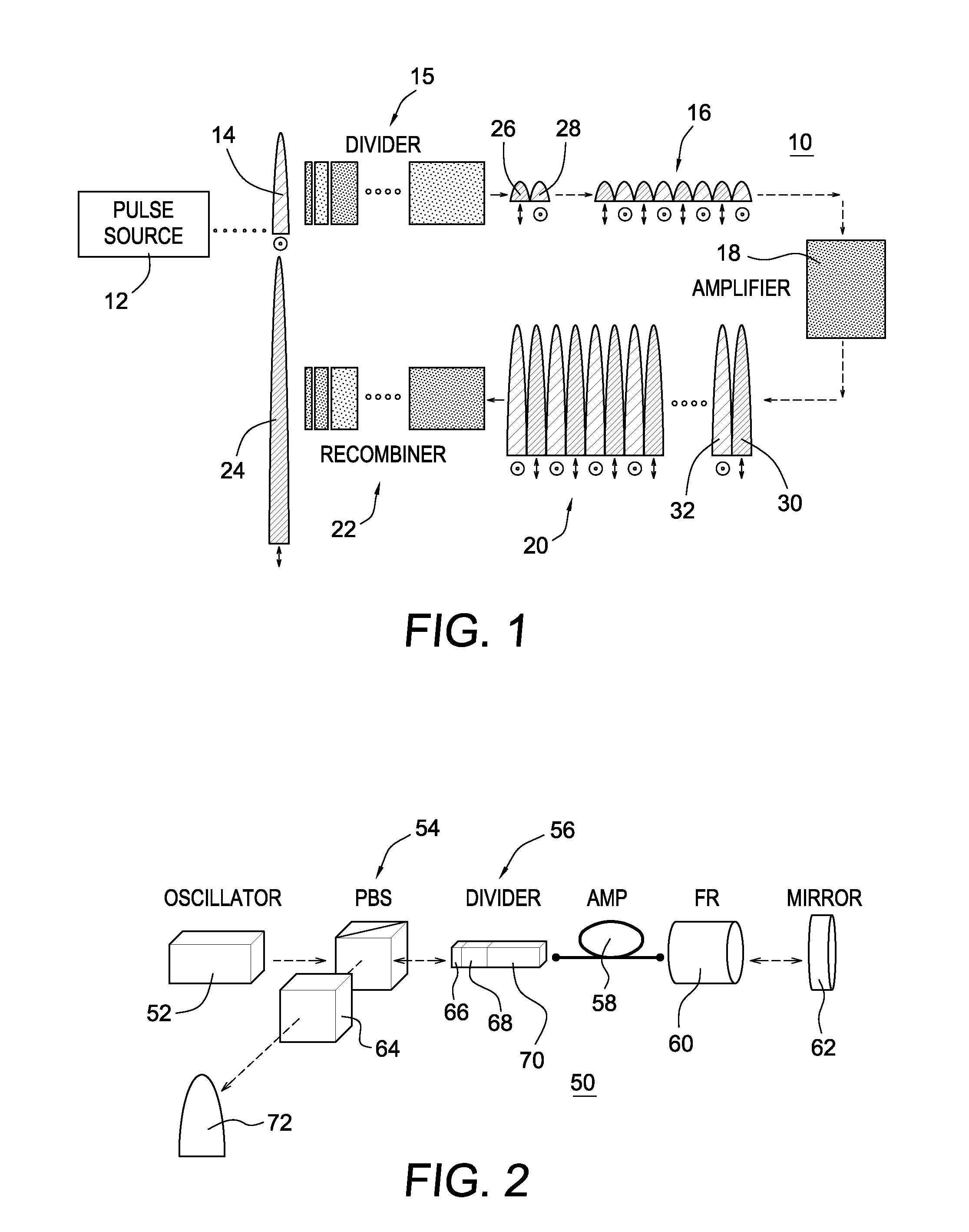
[0019]FIG. 1 is a schematic illustration of a pulse amplifier 10 that is designed to operate in accordance with the DPA principle of the present invention. A pulse source 12, such as a laser oscillator, generates a pulse 14 to be amplified. The pulse 14 is first fed though a pulse divider 15 which divides the original pulse 14 into N smaller copies of itself. N is dependent on the number of divider stages M, where N=2M. The N pulses form a sequence of pulses 16 which is amplified in one or more amplifier stages 18 having a gain G. Finally, the N amplified pulses 20 are passed through a recombiner 22 which combines the amplified pulses 20 to form one large amplified pulse 24. The pulse 24 is a version of the original pulse 14 that has been amplified by the factor G.

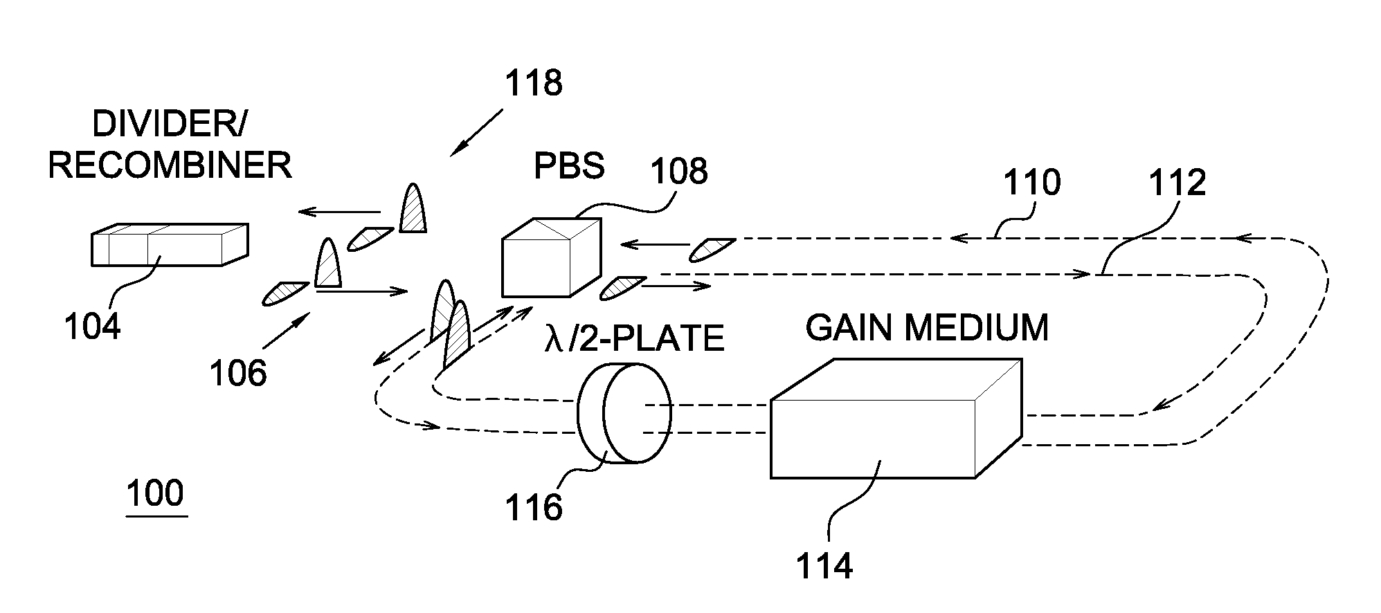
[0020]An essential component of DPA is the process of pulse division and recombination. It is known, theoretically that a pulse can be split and then recombined in a birefringent crystal. One embodiment of the present inve...


PUM


Abstract

To avoid harmful nonlinear effects in the amplification of short optical pulses, an initial pulse is divided into a sequence of lower-energy temporally spaced pulses that are otherwise identical to the original pulse. The low-intensity pulses are amplified and then recombined to create a final amplified output pulse.

Description

GOVERNMENT SPONSORSHIP STATEMENT[0001]The work on this invention was supported by the National Science Foundation under Grant No. ECS-0500956 and PHY-0131508. The Government has certain rights in the invention.BACKGROUND OF THE INVENTION[0002]1. Field of the Invention[0003]The present invention relates in general to a short-pulse amplification technique which reduces or avoids nonlinear effects, thus allowing higher pulse energies without pulse distortion. A pulse to be amplified is divided into a selected number of smaller magnitude pulses that are otherwise identical in shape to the original pulse. The pulses are amplified and then recombined coherently to produce a final output pulse that is an amplified version of the original pulse.[0004]2. Description of the Background Art[0005]Ultrashort light pulses on the order of picoseconds or shorter are now finding application in a wide range of science and technology. Many applications require high-energy pulses, which are obtained by ...

Claims


Application Information

Patent Timeline
Patent Type & Authority Applications(United States)
IPC IPC(8): H01S3/00
CPCH01S3/0057H01S3/2333H01S3/0085
Inventor WISE, FRANK W.ZHOU, SHIANOUZOUNOV, DIMITRE G.
Owner CORNELL UNIVERSITY
Why Eureka
Try Eureka