Optical image measuring device, optical image measuring program, fundus observation device, and fundus observation program

a technology of optical image and measuring device, applied in the field of optical image measuring program, fundus observation device, etc., can solve the problems of conventional optical image measuring device, image distortion, image accuracy impairment, etc., and achieve high accuracy image, high accuracy image, and high accuracy image

Active Publication Date: 2010-06-10
KK TOPCON
View PDF5 Cites 55 Cited by
  • Summary
  • Abstract
  • Description
  • Claims
  • Application Information

AI Technical Summary

Benefits of technology

[0019]According to the optical image measuring device and the optical image measuring program related to the present invention, since a scanning means is configured to scan said signal light in the given direction crossing with said main scanning direction and an image processing means is configured to form a tomographic image for correction along said given direction and correct displacement of each of said two or more formed tomographic images based on said tomographic image for correction, displacement of each tomographic image can be corrected even if the object to be measured moves during scanning of the signal light (light beam), and thus, a highly accurate image can be formed.
[0020]According to the fundus observation device and the fundus observation program related to the present invention, an integrated image is generated by integrating a tomographic image formed by the second image forming means in the depth direction, and displacement in the direction perpendicular to the depth direction of this integrated image based on the 2-dimensional image formed by the first image forming means. Further, they function so as to correct displacement of the tomographic image in the direction perpendicular to the depth direction based on the detected displacement. As a result, since displacement in the direction perpendicular to the depth direction of the tomographic im

Problems solved by technology

Hei11-325849) occurs, resulting in distortion of the image.
If the position of a living eye is displaced by, for example, a heartbeat or eye movement during scanning, the formed image will be distorted in the displacement direction of the living eye o

Method used


Image

  • Optical image measuring device, optical image measuring program, fundus observation device, and fundus observation program
  • Optical image measuring device, optical image measuring program, fundus observation device, and fundus observation program
  • Optical image measuring device, optical image measuring program, fundus observation device, and fundus observation program

Examples


embodiment 2

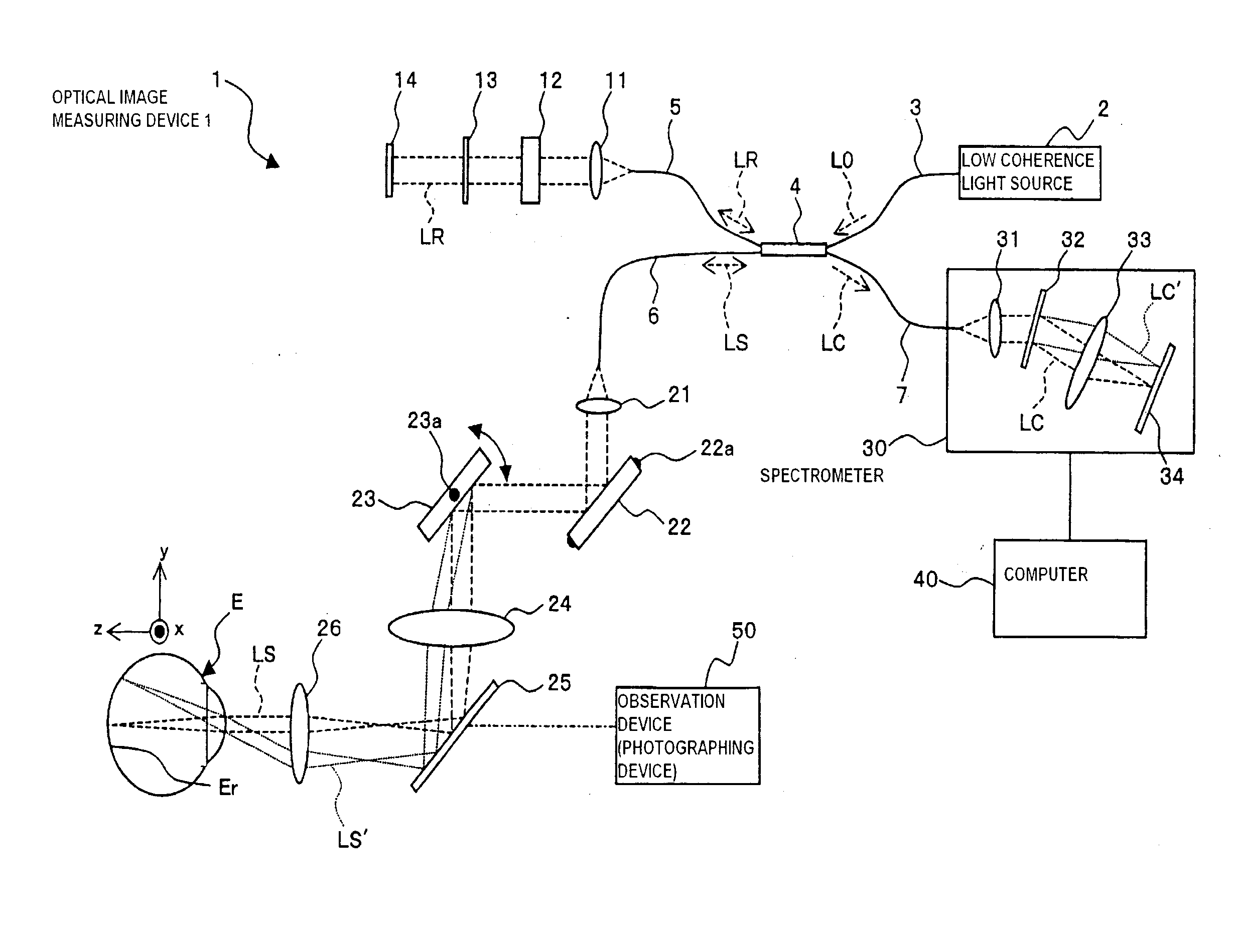
[0172]Next, one example of the preferred embodiments of a fundus observation device and fundus observation program related to the present invention is described.

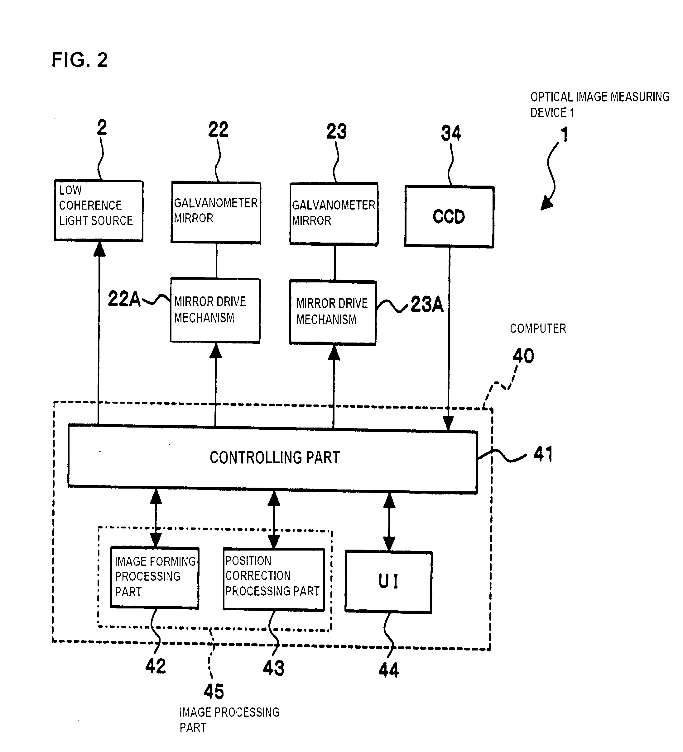
[0173]First, the constitution of the fundus observation device of the present embodiment is explained referring to FIGS. 13 to 17. FIG. 13 shows the entire constitution of a fundus observation device 1000 related to the present embodiment. FIG. 14 shows the constitution of a scan unit 1141 in the fundus camera unit 1000A. FIG. 15 shows the constitution of an OCT unit 1150. FIG. 16 shows the hardware configuration of a computer 1200. FIG. 17 shows the constitution of a control system of the fundus observation device 1000.

Entire Constitution

[0174]As shown in FIG. 13, the fundus observation device 1000 is comprised of a fundus camera unit 1000A that functions as a fundus camera, an OCT unit 1150 accommodating the optical system of an optical image measuring device (OCT device), and a computer 1200 that executes various control ...

modified example

[0271]The constitution described above is merely one example to preferably implement the image observation device of the present invention. Therefore, optional modifications may be implemented appropriately within the scope of the present invention. Hereinafter, one example of such modifications is explained.

[0272]First, although displacement correction in both the xy-direction and z-direction are performed in the above embodiment, it is possible to be configured to perform displacement correction in only the xy-direction. In that case, the z position correction processing part 1228 does not have to be provided in the block diagram of FIG. 18.

[0273]In addition, it is also possible to be configured to perform displacement correction in only the x-direction, or perform displacement in only the y-direction.

[0274]In the present embodiment described above, the fundus image is adapted to be photographed before performing the optical image measurement, but the timing to photograph the fund...


PUM


Abstract

An optical image measuring device which can form a highly reliable image even if an object moves during scanning of a signal light is provided. An optical image forming device 1 comprises: an interferometer that splits a low coherence light L0 into a signal light LS and a reference light LR and generates an interference light LC by overlaying the signal light LS reflected by a fundus oculi with the reference light LR reflected by a reference mirror 14; a CCD 34 which receives the interference light LC and outputs a detection signal; Galvanometer mirrors 22 and 23 to scan the signal light LS in a main scanning direction and a sub-scanning direction; and a computer 40 forming tomographic images G1 to Gm along the main scanning direction at different positions of the sub-scanning direction. The Galvanometer mirrors 22 and 23 scan the signal light LS in a given direction crossing the main scanning direction, and the computer 40 forms a tomographic image for correction GR along the given direction to correct displacement of each topographic image Gi based on the tomographic image for correction GR.

Description

BACKGROUND OF THE INVENTION[0001]1. Field of the Invention[0002]The present invention particularly relates to an optical image measuring device and an optical image measuring program that irradiates a light beam on an object to be measured comprising a light scattering medium and measures the surface and internal morphology of the object to be measured using the reflection light or transmitted light to form images of the object to be measured, and further relates to a fundus observation device and fundus observation program comprising this optical image measuring device for observing a fundus oculi of an eye to be examined.[0003]2. Description of the Related Art[0004]Optical image measuring technology which forms an image showing the surface and internal morphology of the object to be measured using a light beam from a laser source has received attention in recent years. This optical image measuring technology is expected to be developed especially in the medical field because the t...

Claims


Application Information

Patent Timeline
IPC IPC(8): G06K9/00
CPCA61B3/102G01N2021/1787G01N21/4795A61B3/145
Inventor YASUNO, YOSHIAKIYATAGAI, TOYOHIKOFUKUMA, YASUFUMITSUKADA, HISASHIKIKAWA, TSUTOMUAOKI, HIROYUKIFUJIMURA, TAKASHI
Owner KK TOPCON
Why Eureka
Try Eureka