
Prismatic-cell battery pack with integral coolant passages

a battery pack and coolant passage technology, applied in the field of high-voltage battery packs, can solve the problems of reducing the heat rejection capability at the downstream end of the heatsink, affecting the efficiency of the battery pack, and affecting the power output of the battery pack

Active Publication Date: 2010-06-10
DELPHI TECH IP LTD
View PDF2 Cites 33 Cited by
  • Summary
  • Abstract
  • Description
  • Claims
  • Application Information

AI Technical Summary

Benefits of technology

The present invention is about an improved battery pack that has coolant channels to remove heat from the battery cells. The battery pack is made up of interlocking battery cell modules that have coolant channels distributed over their profile. Each module has intake and exhaust plenums to form the coolant flow. The coolant channels are in the shape of an inverted-U, conducting coolant from the intake plenum upward towards the battery cell terminals and then back downward to enter the exhaust plenum. The technical effect of this invention is to improve the performance and longevity of prismatic-cell battery packs.

Problems solved by technology

A serious challenge involved in the design of a battery pack is the provision of adequate cooling for the individual cells.
While this approach can be effective if sufficient space is available to accommodate the heatsinks, space and weight considerations often take precedence, forcing sub-optimal sizing and placement of the heatsinks.
Moreover, the effectiveness of this approach is hampered for two additional reasons: first, the heat produced in a battery cell is greatest near its terminals, which may be separated from the heatsinks by a substantial distance; and second, the cooling medium rises in temperature as it travels through the heatsink, which degrades heat rejection capability at the downstream end of the heatsink.
And since over-heating can permanently damage a battery cell, the power output of the battery pack often has to be limited to preserve battery pack life expectancy.

Method used


Image

  • Prismatic-cell battery pack with integral coolant passages
  • Prismatic-cell battery pack with integral coolant passages
  • Prismatic-cell battery pack with integral coolant passages

Examples


Embodiment Construction

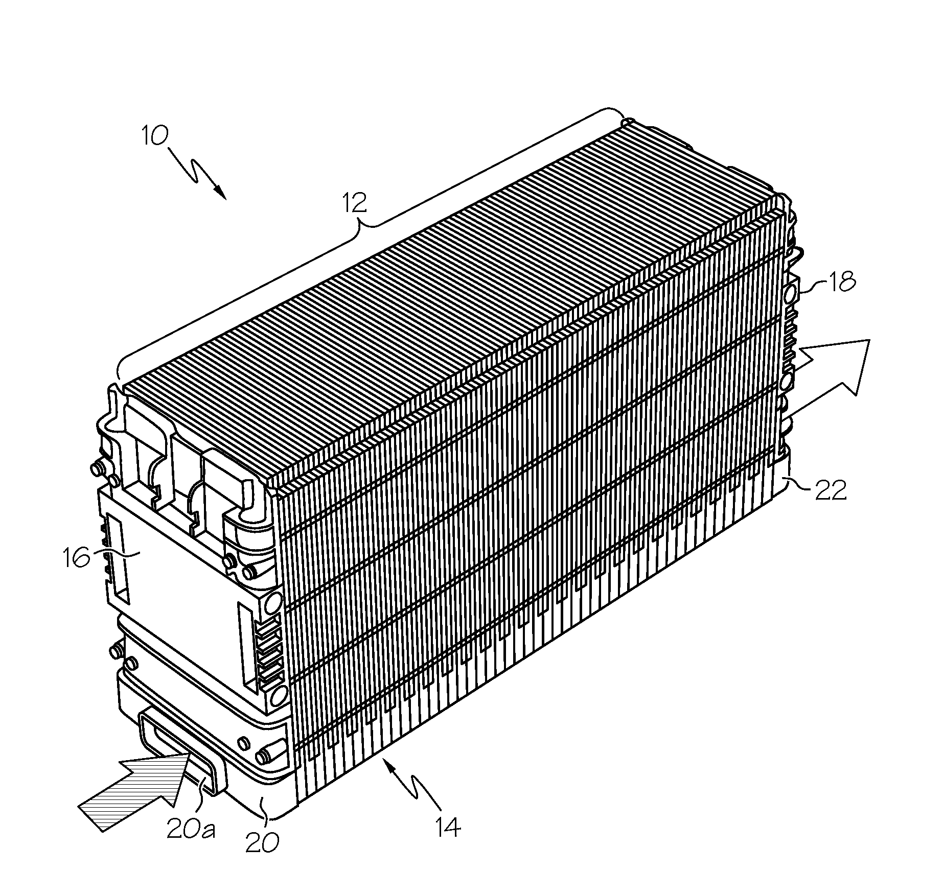
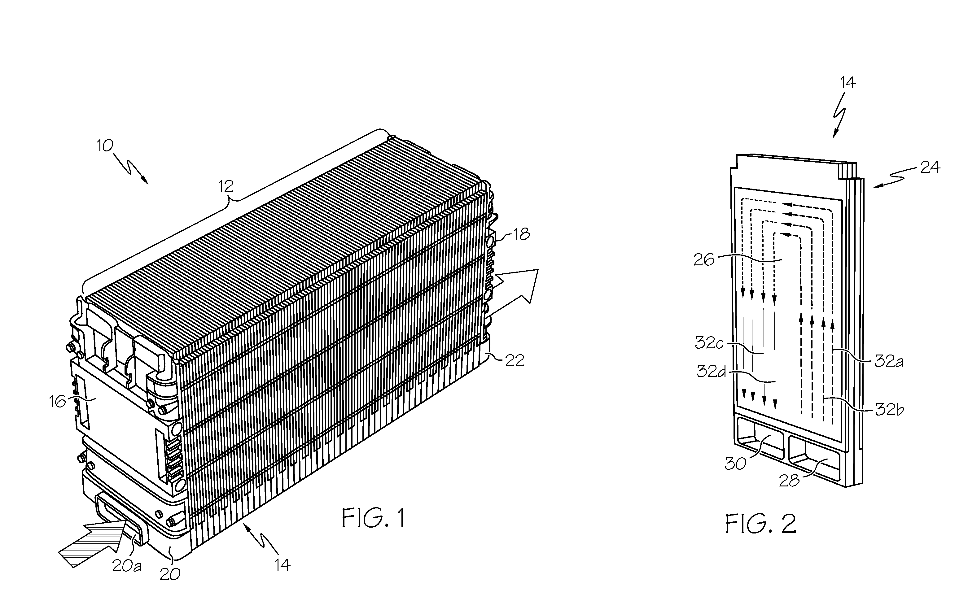
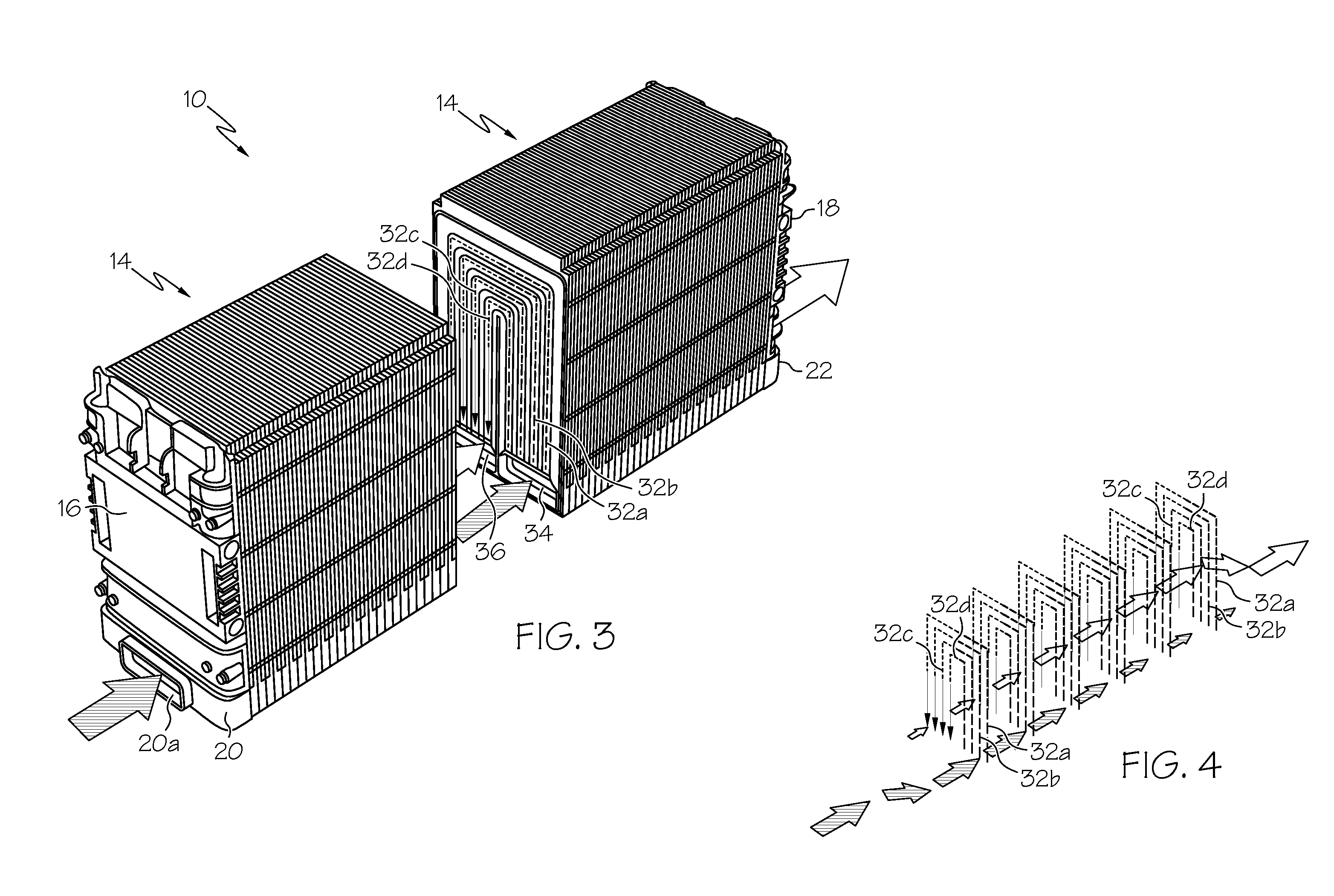
[0012]Referring to the drawings, and particularly to FIGS. 1-3, the reference numeral 10 generally designates prismatic-cell battery pack according to this invention. In general, the battery pack 10 includes a lineal stack 12 of battery cell modules 14 longitudinally bounded by first and second end pieces 16 and 18, an inlet end cap 20, and an outlet end cap 22. Referring particularly to FIG. 2, each of the battery cell modules 14 includes a set of interlocking frames 24 for supporting and retaining a pair of prismatic battery cells 26 (only one of which is shown in FIG. 2), and for channeling coolant in proximity to the battery cells 26. The battery cells 26 are preferably soft-package cells, and a pad of resilient material such as open-cell foam (not shown) is inserted between each of the battery cell modules 14 of the stack 12 to support and compressively load the non-marginal portions of the battery cells 26. The battery pack elements may be held in place, for example, by a set ...


PUM

PropertyMeasurementUnit
thicknessaaaaaaaaaa
voltageaaaaaaaaaa
weightaaaaaaaaaa

Abstract

A prismatic-cell battery pack is provided with integral coolant passages including an intake plenum, an exhaust plenum, and a distributed array of coolant channels coupled between the intake plenum and the exhaust plenum. Coolant medium forced into the intake plenum enters the coolant channels in parallel, draws heat away from the battery cells, and then enters the exhaust plenum for expulsion into the atmosphere. The battery pack is configured as a set of stackable interlocking battery cell modules including at least one battery cell in thermal proximity to an array of coolant channels distributed over the profile of the battery cell, and a pair of peripheral chambers joined to opposite ends of the coolant channels to form the intake and exhaust plenums when the modules are arranged and interlocked in a lineal stack.

Description

TECHNICAL FIELD[0001]The present invention relates to a high-voltage battery pack containing prismatic battery cells arranged a lineal stack, and more particularly to prismatic-cell battery pack with integral coolant passages for forced-air cooling of the battery cells.BACKGROUND OF THE INVENTION[0002]High voltage battery packs can be configured for efficient space utilization by stacking and co-packaging battery cells of a prismatic (i.e., rectangular) form factor. The prismatic cells are typically arranged so that their terminals are all accessible from the top of the pack, and the terminals of adjacent cells lie in close proximity for convenient interconnection due to the thin profile of the cells. Lithium-ion batteries are well-suited to such applications because of their low weight, high power density and relatively high cell voltage, and because they can be produced at relatively low cost in prismatic form, particularly when encapsulated by a soft package of metalized plastic ...

Claims


Application Information

Patent Timeline
Patent Type & Authority Applications(United States)
IPC IPC(8): H01M10/50
CPCH01M6/42H01M10/5004H01M10/5008H01M10/5016H01M10/5073H01M10/5038H01M10/5059H01M10/5067H01M10/5032H01M10/613H01M10/617H01M10/625H01M10/647H01M10/652H01M10/6557H01M10/6563H01M10/6566Y02E60/10
Inventor KRUGER, DUANE D.BEER, ROBERT C.
Owner DELPHI TECH IP LTD
Learn More