Data transmission method, serial bus system, and switch-on unit for a passive station

a data transmission and serial bus technology, applied in the direction of transmission, memory adressing/allocation/relocation, programme control, etc., can solve the problems of reducing the efficiency of data transmission, requiring a high processing effort, and unable to achieve optimal bus use, so as to achieve the optimal bus use, reduce the effort of data processing in the active station, and save considerable time

Inactive Publication Date: 2010-06-10
BECKHOFF AUTOMATION GMBH
View PDF22 Cites 6 Cited by
  • Summary
  • Abstract
  • Description
  • Claims
  • Application Information

AI Technical Summary

Benefits of technology

[0020]According to the invention, the design of the serial bus or the data transmission onto this serial bus, for which each station can use its switch-on unit to remove or insert any pre-configured data into a data flow transmitted in the form of telegrams, provides high flexibility for the data transmission between the stations with simultaneously low data processing effort. In particular, a simplified process data transmission of control applications is possible between decentralized devices attached to the serial bus.
[0024]Furthermore, the configuration according to the invention avoids a complicated mapping process in the active station, with which the process data allocated to the individual passive stations is correlated with the corresponding process images of the control application. The mapping process is already performed in the passive stations themselves, namely by means of the allocation table, wherein the data processing effort in the active station is significantly reduced and thus considerable time savings are achieved when performing the control tasks. In addition, the device and implementation effort is significantly reduced by shifting the allocation process into the passive stations.
[0025]According to a preferred embodiment, in the interface unit of the passive station the stored allocation table is divided into register data sets, each of which gives a logical address of data transmitted by the serial bus in a telegram, a physical address of the data memory allocated to the data in the passive station, and a data transmission mode. The configuration according to the invention of the mapping process and of the data transmission in the passive station provides an especially simple and fast-acting allocation process for only a small implementation and protocol effort in the passive station. In particular, with this design of the allocation process it is possible in the passive station to perform the data transfer between the telegrams circulating on the serial bus and the data memories allocated to the corresponding passive stations in a simple way.
[0026]According to another preferred embodiment, the allocation table in the passive station is generated during an initialization phase, wherein the active station reports to the passive station the logical addresses of data relevant for the passive station in the individual telegrams and the passive station then correlates the logical addresses with the corresponding physical address of data memories. This configuration enables high flexibility for the data transmission, and in particular adaptation to the respective desired control application. It can be individually reported to the passive stations which process data is transmitted from the active station, i.e., by the control device, and where this process data is located in the telegrams circulating on the serial bus.

Problems solved by technology

However, this allocation, which is also called mapping in the following, of process data of the slave devices to the process images, which are used in the master device and which are formed in the field-bus switch-on device of the master device, requires a high processing effort.
The required conversion of the process data of the individual slave devices into process images in the field-bus controller also leads to significantly delayed processing of processes, especially when several tasks are supposed to be performed simultaneously.
Furthermore, if the individual partial processes have different cycle times, conventional data transmission methods on the field bus cannot adapt the bus load to the individual partial processes according to the different cycle times, and thus cannot achieve an optimal use of the bus.
In addition, conventional field-bus systems can only with much difficulty provide flexible adaptation of the telegrams to the process data lengths required in the slave devices.

Method used


Image

  • Data transmission method, serial bus system, and switch-on unit for a passive station
  • Data transmission method, serial bus system, and switch-on unit for a passive station
  • Data transmission method, serial bus system, and switch-on unit for a passive station

Examples


Embodiment Construction

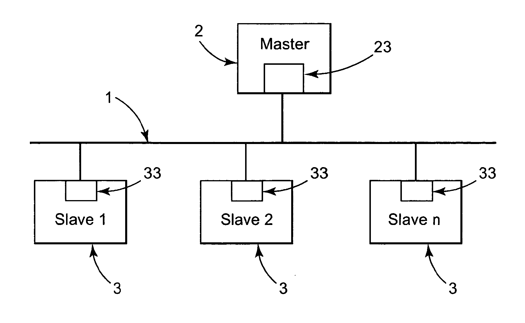
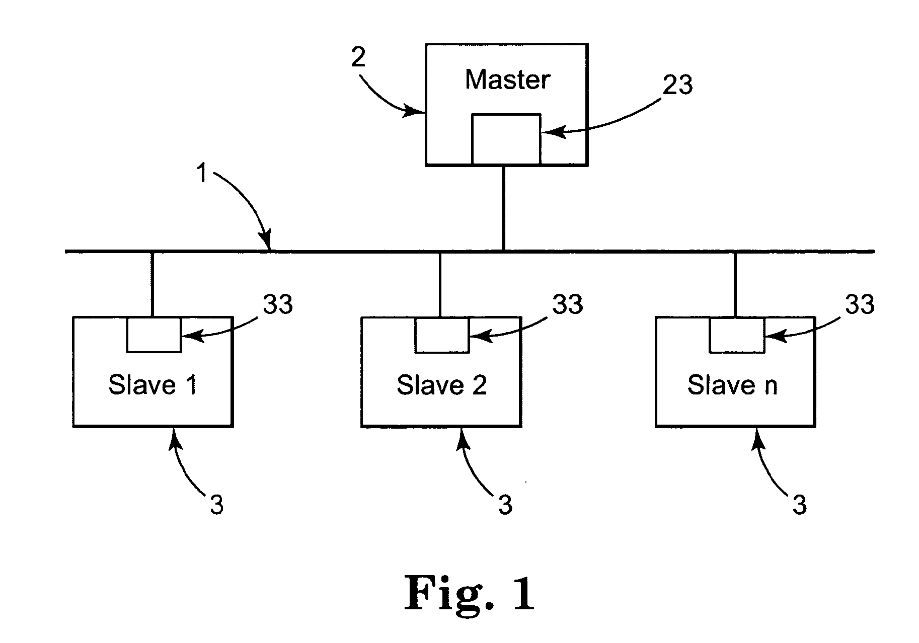
[0035]More and more field-bus systems are being used in automation technology, wherein distributed devices of the peripheral machines communicate with automation, engineering, and visualization systems by means of a field bus. One such field-bus system is shown in FIG. 1.

[0036]The field-bus system has a serial bus 1, which can be, e.g., an electrical line, an optical fiber, or also a radio cable. All of the stations are attached to this bus 1, wherein a distinction can be made between active and passive stations. The active stations on the field-bus system are the master devices 2, which determine the data traffic on the bus. One such master device is, e.g., an industrial PC, which operates as a process control computer in a manufacturing process. This master device 2 has a bus access token and can output data onto the bus 1 without an external request. The passive stations on the bus system are the peripheral machines, e.g., I / O devices, valves, drives, and measurement transducers....


PUM


Abstract

In a serial bus system data in the form of telegrams, representing process images of control tasks of the active station, are transmitted to the connected passive stations, and the process data are allocated to the process images in the passive station.

Description

CROSS REFERENCE TO RELATED APPLICATIONS[0001]This application is a continuation of U.S. patent Application Ser. No. 10 / 499,724, filed Jun. 21, 2004, titled DATA TRANSMISSION METHOD, SERIAL BUS SYSTEM, AND SWITCH-ON UNIT FOR A PASSIVE STATION, which claims priority to International Application No. PCT / EP02 / 14423 filed on Dec. 17, 2002, which claims priority to German patent application DE 101 63 342.4 filed on Dec. 21, 2001, all of which are incorporated herein by reference in their entireties.FIELD OF THE INVENTION[0002]The invention relates to a method for transmitting data on a serial bus between at least one active station and at least one passive station, to a correspondingly configured serial bus system, and to a switch-on unit for a passive station in such a serial bus system.BACKGROUND OF THE INVENTION[0003]Serial bus systems are being used more and more for production and process automation, wherein the decentralized devices of peripheral machines, such as I / O modules, measu...

Claims


Application Information

Patent Timeline
Patent Type & Authority Applications(United States)
IPC IPC(8): G06F13/40G05B19/042
CPCG05B19/042
Inventor BECKHOFF, HANSBUTTNER, HOLGER
Owner BECKHOFF AUTOMATION GMBH
Why Eureka
Try Eureka