LNG Regasification And Power Generation

a technology of liquefied natural gas and power generation, which is applied in the direction of machines/engines, mechanical equipment, and containers with discharge methods, etc., can solve the problems of high heat transfer fluid circulation rate, difficult operation and control of such multi-component systems, and limited use of cryogenic refrigeration content of lng

Inactive Publication Date: 2010-06-17
FLUOR TECH CORP
View PDF10 Cites 28 Cited by
  • Summary
  • Abstract
  • Description
  • Claims
  • Application Information

AI Technical Summary

Benefits of technology

[0007]The present invention is directed to configurations and methods of regasification of LNG with concurrent power production, preferably using ambient air, sea water, or other low-grade heat sources. Most preferably, power is generated using a multi-stage Rankine cycle in which the working fluids are expanded over at least

Problems solved by technology

While such a configuration increases efficiency of a plant to some degree, several problems remain.
For example, the utilization of the cryogenic refrigeration content of the LNG is often limited due to the relatively high freezing point of the heat transfer medium.
However, operation and control of such multi-component system is complex, difficult, and often impractical.
However, these configurations typically require high circulation rates of the heat transfer fluid and further require a heater to boost the temperature of the vaporized LNG to pipeline specification.
Therefore, while some of the known configurations improve efficiency of power generation to some extent

Method used


Image

  • LNG Regasification And Power Generation
  • LNG Regasification And Power Generation
  • LNG Regasification And Power Generation

Examples


Embodiment Construction

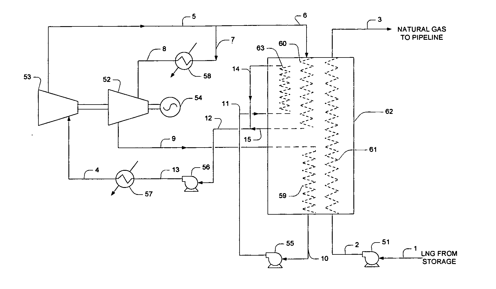
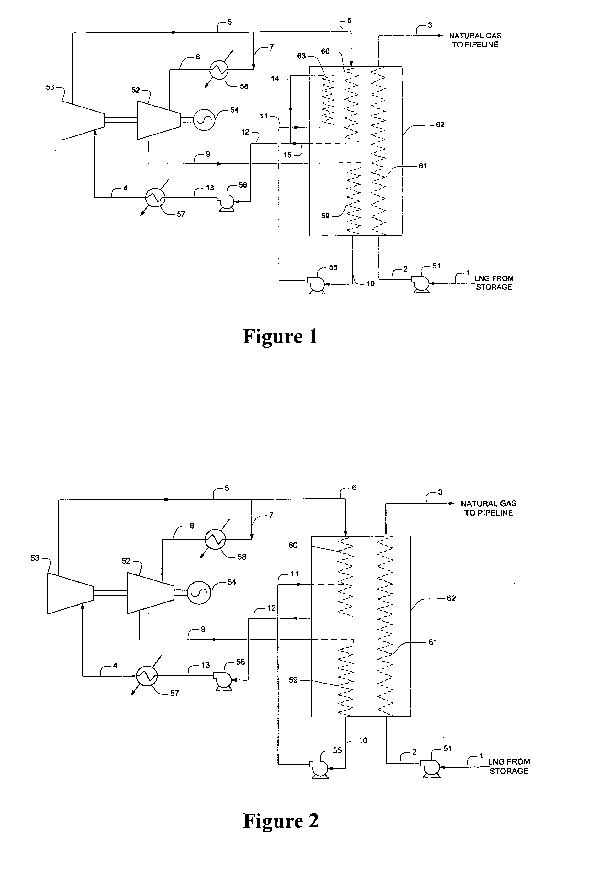
[0019]The inventor has discovered that refrigeration content of LNG can be advantageously employed in the production of power in an LNG regasification facility by using a working fluid in a multi-stage Rankine cycle configuration, wherein the LNG is regasified in at least two heat exchange stages, and wherein each of the exchange stages receives expanded working fluid vapors from respective turbines or turbine stages. In particularly preferred configurations, that the intermediate-pressure working fluid is condensed using refrigeration content of both warmed LNG (produced by condensation of low-pressure working fluid) and low-pressure working fluid condensate, and that the working fluid is heated by various low temperature heating sources.

[0020]Therefore, it should be recognized that LNG regasification and power generation may be accomplished with the use of ambient air vaporizers, seawater vaporizers, and / or waste heat, and without the use of fuel gas. Moreover, such configurations...


PUM


Abstract

LNG is regasified with concurrent power production in systems and methods where the refrigeration content of the LNG condenses a low pressure working fluid vapor and in which the combined refrigeration content of the warmed LNG and low pressure working fluid condensate condenses an intermediate pressure working fluid vapor.

Description

[0001]This application claims priority to our copending U.S. provisional application with the Ser. No. 60 / 940787, which was filed May 30, 2007.FIELD OF THE INVENTION[0002]The field of the invention is regasification of liquefied natural gas (LNG), especially with concurrent power production.BACKGROUND OF THE INVENTION[0003]Regasification of LNG requires significant quantities of thermal energy, and typical LNG regasification facilities employ external heat sources to vaporize LNG prior to delivery of the gas to existing pipeline networks. For example, external heat sources include sea water, combustion exhaust, waste heat from power generation, and ambient air. Depending on the particular heat source, the LNG vaporizers may be configured as an open rack seawater vaporizer, a submerged combustion vaporizer, an intermediate fluid vaporizer (e.g., using a glycol-water mixture), or as an ambient air vaporizer. Furthermore, LNG regasification also requires a reliable power supply to oper...

Claims


Application Information

Patent Timeline
IPC IPC(8): F01K25/08F01K7/16F17C9/02F01K9/00F01K23/02
CPCY02E10/34F01K13/00Y02E20/16F17C7/04F17C2221/033F17C2223/0161F17C2223/033F17C2225/0123F17C2225/036F17C2227/0309F17C2227/0313F17C2227/0316F17C2227/0318F17C2227/0323F17C2227/0332F17C2227/0397F17C2265/05Y02E10/30
Inventor MAK, JOHN
Owner FLUOR TECH CORP
Why Eureka
Try Eureka