Multi-cylinder rotary compressor and refrigeration cycle equipment

a rotary compressor and refrigeration cycle technology, applied in the direction of domestic cooling equipment, lighting and heating equipment, liquid fuel engines, etc., can solve the problems of reliability and performance problems, reduce the rigidity of connecting parts, etc., and achieve the effect of facilitating assembly work

Active Publication Date: 2010-06-17
TOSHIBA CARRIER CORP
View PDF7 Cites 22 Cited by
  • Summary
  • Abstract
  • Description
  • Claims
  • Application Information

AI Technical Summary

Benefits of technology

[0015]According the technique disclosed in Jpn. Pat. Appln. KOKAI Publication No. 2003-328972, a configuration expressed by the above formula Rc<Rm+e is possible, and it is possible to insert a roller from the end face of a countershaft, pass over a crankshaft provided in the countershaft, and fitted to the crankshaft of the main shaft after once placing in a connecting part. Thereafter, another roller is fitted to the crankshaft of the countershaft. This facilitates the assembling work.
[0017]Therefore, particularly when the axial length of the roller fitted to the crankshaft of the main shaft is greater, it is necessary to provide a connecting part whose axial length is greater than that of the roller, and the distance between the crankshafts becomes large. This decreases the rigidity of the connecting part, and causes a problem in the reliability and performance.
[0018]On the other hand, in the technique described in Jpn. UM Appln. KOKOKU Publication No. 55-48887, the cross-sectional area of the connecting part can be made greater than that in the prior art, and the rigidity is improved. However, in this technique, a large diameter part of a connecting rod is connected to a crankshaft, and the axial length (thickness) of the large diameter part is made less than that of the connecting part.
[0020]The invention has been performed in the above circumstances. It is an object of the invention to provide a multi-cylinder rotary comprising two or more compression mechanisms, in which a roller to be fitted to a crankshaft of a main shaft is inserted from the direction of the end face of a countershaft, the crankshaft diameter is decreased as much as possible to reduce sliding loss, the axial length of a connecting part, which is the distance between the crankshafts, is reduced, and the compression mechanism is made compact, thereby the compression performance and reliability are improved, and refrigeration cycle equipment which comprises the multi-cylinder rotary compressor for improving refrigeration efficiency and reliability.

Problems solved by technology

This decreases the rigidity of the connecting part, and causes a problem in the reliability and performance.

Method used


Image

  • Multi-cylinder rotary compressor and refrigeration cycle equipment
  • Multi-cylinder rotary compressor and refrigeration cycle equipment
  • Multi-cylinder rotary compressor and refrigeration cycle equipment

Examples


first embodiment

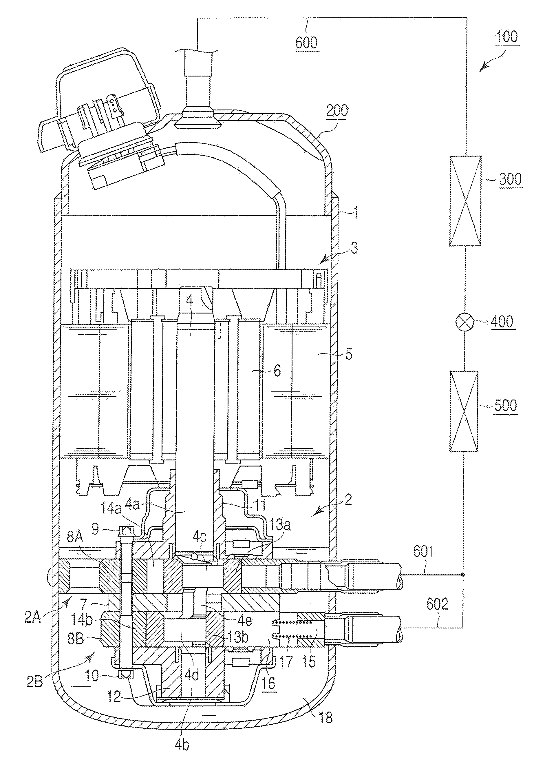
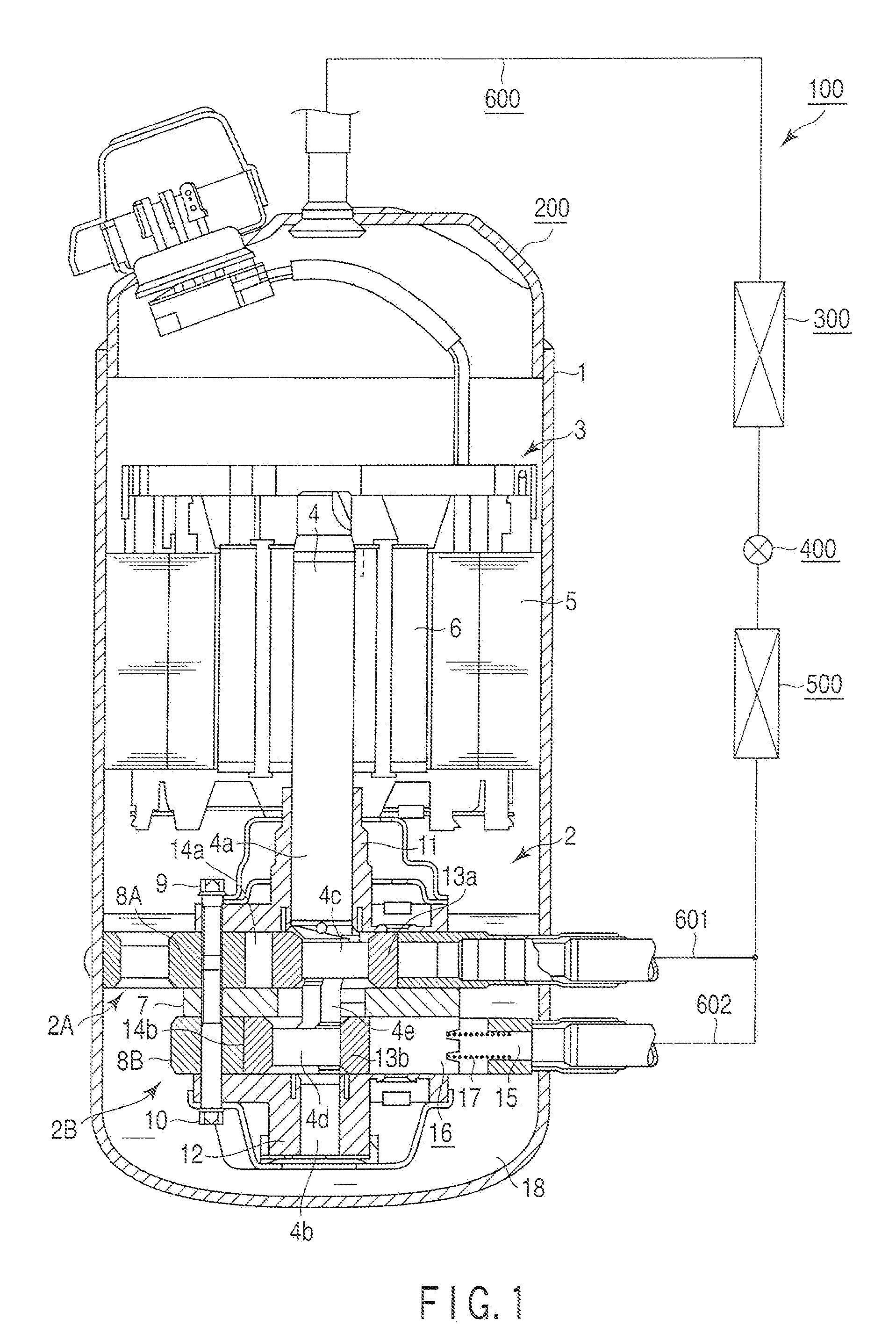
[0048]Embodiments of the invention will be explained hereinafter with reference to the accompanying drawings. FIG. 1 shows a sectional view of a structure of a multi-cylinder rotary compressor 200 according to the invention, and an outline block diagram of refrigeration cycle equipment R comprising the multi-cylinder rotary compressor 200.

[0049]First, a configuration of the refrigeration equipment R will be explained. The refrigeration equipment R comprises a multi-cylinder rotary compressor 200, a condenser 300, an expansion device 400, an evaporator 500, and a not-shown gas-liquid separator. These components are sequentially communicated through a refrigerant pipe 600. As described later, refrigerant gas compressed by the multi-cylinder rotary compressor 200 is discharged to the refrigerant pipe 600, circulated through the above components, forming a refrigeration cycle, and fed back to the multi-cylinder rotary compressor 200.

[0050]Next, the multi-cylinder rotary compressor 200 w...

second embodiment

[0106]FIG. 6 is a sectional view of a part of a multi-cylinder rotary compressor 210 according to a

[0107]In the compressor 210, as in the first embodiment, first and second compression mechanisms 2A and 2B are connected together with a motor unit 3 through a rotary shaft 4, and housed in a sealed case 1. The configuration of the motor unit 3 is the same as that in the first embodiment. The first and second compression mechanisms 2A and 2B are basically the same as those in the first embodiment. Main components are denoted by the same reference numbers, and an explanation thereof is omitted.

[0108]In the compression mechanism 2, a main bearing 11a is formed in one piece with a frame 25 press fitted to the sealed case 1, and a first cylinder 8A is fixed to the lower surface of the frame 26. An intermediate partition board 7A is made thick. A suction hole 26 is formed penetrating a part of the sealed case 1 and the outer periphery of the intermediate partition board 7A.

[0109]The suction...

third embodiment

[0148]FIG. 11 is a longitudinal sectional view of a multi-cylinder rotary compressor 230, omitted in some parts, according to a

[0149]Except for a connecting part 4g described later, the component parts are the same as those of the multi-cylinder compressor 210 explained in the second embodiment (FIG. 6). The same parts are denoted by the same number, and an explanation thereof is omitted. In the compressor 210, the blade chamber 15, blade 16, and spring member 17 are not shown in the drawing. In the compressor 230, these parts are shown in being fitted to the first cylinder 8A.

[0150]As in the multi-cylinder rotary compressor 210 in the second embodiment, comparing with the intermediate partition board 7 of the multi-cylinder rotary compressor 200 in the first embodiment, the thickness of the intermediate partition board 7A is increased, and the axial length of the connecting part 4g of the rotary shaft 4 provided oppositely to the intermediate partition board 7A is increased by the ...


PUM


Abstract

A rotary compressor, in which formulas Rc<Rm+e and RC≧Rs+e are established, when the radius of a main shaft is Rm, the radius of a countershaft is Rs, the radius of a crankshaft is Rc, and the eccentricity is e, a connecting part has a A-periphery which is formed on the counter-eccentric side periphery of the second crankshaft, and a B-periphery formed on the counter-eccentric side periphery of a first crankshaft, and a formula H>L≧H−Cr−Cs is established, when the axial direction of the connecting part is L, the axial length of the first roller is H, the axial length of a bevel formed at the inside edge of the first roller is Cr, and the axial direction of a bevel of the second crankshaft is Cs.

Description

CROSS-REFERENCE TO RELATED APPLICATIONS[0001]This is a Continuation Application of PCT Application No. PCT / JP2008 / 065461, filed Aug. 28, 2008, which was published under PCT Article 21(2) in Japanese.[0002]This application is based upon and claims the benefit of priority from prior Japanese Patent Application No. 2007-221616, filed Aug. 28, 2007, the entire contents of which are incorporated herein by reference.BACKGROUND OF THE INVENTION[0003]1. Field of the Invention[0004]The present invention relates to a multi-cylinder rotary compressor provided with an improved compression mechanism, and refrigeration cycle equipment using the multi-cylinder rotary compressor for making a refrigeration cycle.[0005]2. Description of the Related Art[0006]Refrigeration cycle equipment comprising a refrigeration circuit uses various types of compressor. For example, an air-conditioner often uses a multi-cylinder rotary compressor, or a two-cylinder compressor. Such a type of compressor has a sealed ...

Claims


Application Information

Patent Timeline
Patent Type & Authority Applications(United States)
IPC IPC(8): F25D9/00F16C3/18
CPCF04C18/356F04C23/001Y10T74/2173F04C2250/00F04C23/008F04C2240/60
Inventor HIRAYAMA, TAKUYA
Owner TOSHIBA CARRIER CORP
Why Eureka
Try Eureka