Multi-function frame and integrated mounting system for photovoltaic power generating laminates

a photovoltaic power generating and laminate technology, applied in the direction of heat collector mounting/support, solar heat collector safety, light and heating apparatus, etc., can solve the problems of system inefficiency, module-to-module mismatch, and limitations of current photovoltaic power generating building-mounted systems

Inactive Publication Date: 2010-06-17
GREENRAY
View PDF17 Cites 189 Cited by
  • Summary
  • Abstract
  • Description
  • Claims
  • Application Information

AI Technical Summary

Benefits of technology

[0014]In the preferred embodiment of the invention the laminate is rectangular and the frame is made up of four frame members, with each of two opposed frame members having an integral interface means in the form of a captivating flange that projects outwardly and downwardly and also lengthwise of the outer surface of that frame member. The captivating flanges are shaped so as to define U-shaped channels sized to accept the upper end of one or more support members in a close fit, whereby the module can be positioned on two support members with its dead weight supported entirely by the two support members. The U-shaped channels also allow the points of engagement between the modules and its support members to be shifted in one direction or the other lengthwise of the channels as the module is being mounted on a roof, thereby allowing the module support members to be located directly over the roof rafters. Each of the two opposed frame members also has a flat groove in its outer surface that extends lengthwise parallel to its captivating flange, and each support member comprises screw means for frictionally engaging the bottom of the groove, whereby to lock the module against movement relative to the support members.

Problems solved by technology

Current photovoltaic power generating building-mounted systems have a variety of limitations.
Despite the inverter's ability to track the optimal conversion voltage for the system, the system suffers inefficiencies such as module-to-module mismatch, power loss due to varying module orientation and significant shading losses.
The single inverter only has the ability to optimize the DC to AC conversion efficiency for the array of modules; it cannot optimize conversion from a single module.
With a single inverter for an array of modules, the task of installing and connecting the DC conductors also presents a problem.
The problems noted above have resulted in efforts to integrate a power converter with each solar cell module.
However, the Kobayashi module has limitations as a consequence of the fact that the power converter is physically secured directly to the rear surface of the PV laminate.
Other problems and limitations encountered with prior photovoltaic generating systems are specific to the frame construction of the PV modules and the means for interconnecting and mounting PV modules in an array on a roof.
Problems and limitations with PV module frame construction include designs that make it uncomfortable or awkward for a person to carry or lift a module and / or that make it difficult and costly to mechanically couple modules together for improved mechanical integrity.
Problems and limitations specific to PV mounting systems stem from designs that (a) make it difficult for a person to access centrally located PV modules in a roof array for inspection, repair or replacement, (b) require excessive installation labor, (c) complicate mechanical integration of adjacent modules, (d) introduce air dams that reduce airflow underneath the modules and thereby increase module temperature and reduce module efficiency, (e) make inadequate provision for cable routing, resulting in cables being exposed in position to be damaged by exposure to the environment or by workman working on the rooftop, (f) complicate electrical grounding due to the need to run a separate conductor to each component having metallic surfaces, (g) do not provide an aesthetic appeal, (h) make it difficult to replace modules; and (i) make inadequate provision for avoiding pooled water on the face of the PV modules, resulting in residual sediment that shades the PV cells when the pooled water evaporates.

Method used


Image

  • Multi-function frame and integrated mounting system for photovoltaic power generating laminates
  • Multi-function frame and integrated mounting system for photovoltaic power generating laminates
  • Multi-function frame and integrated mounting system for photovoltaic power generating laminates

Examples


Embodiment Construction

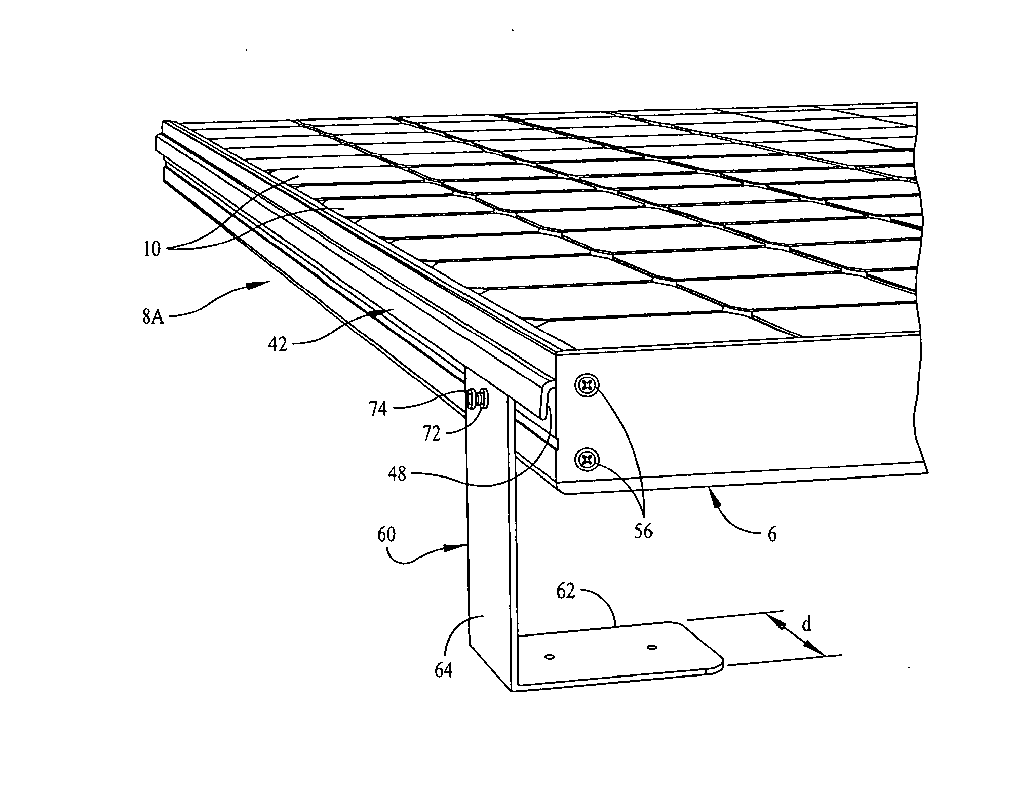
[0045]As used herein, the term “PV” is an acronym for “photovoltaic” and the term “photovoltaic power generating system” means a system comprising one or more PV modules. As used herein, the term “PV module” denotes an assembly of one or more PV laminations and a frame surrounding and supporting the laminate(s). Also a used herein the term “PV laminate” denotes and identifies an integral unit comprising a front transparent panel and a rear supporting panel, a plurality of electrically interconnected photovoltaic cells encapsulated between the front and rear panels, and electrical output means whereby the power generated by the cells can be transmitted for processing and / or use.

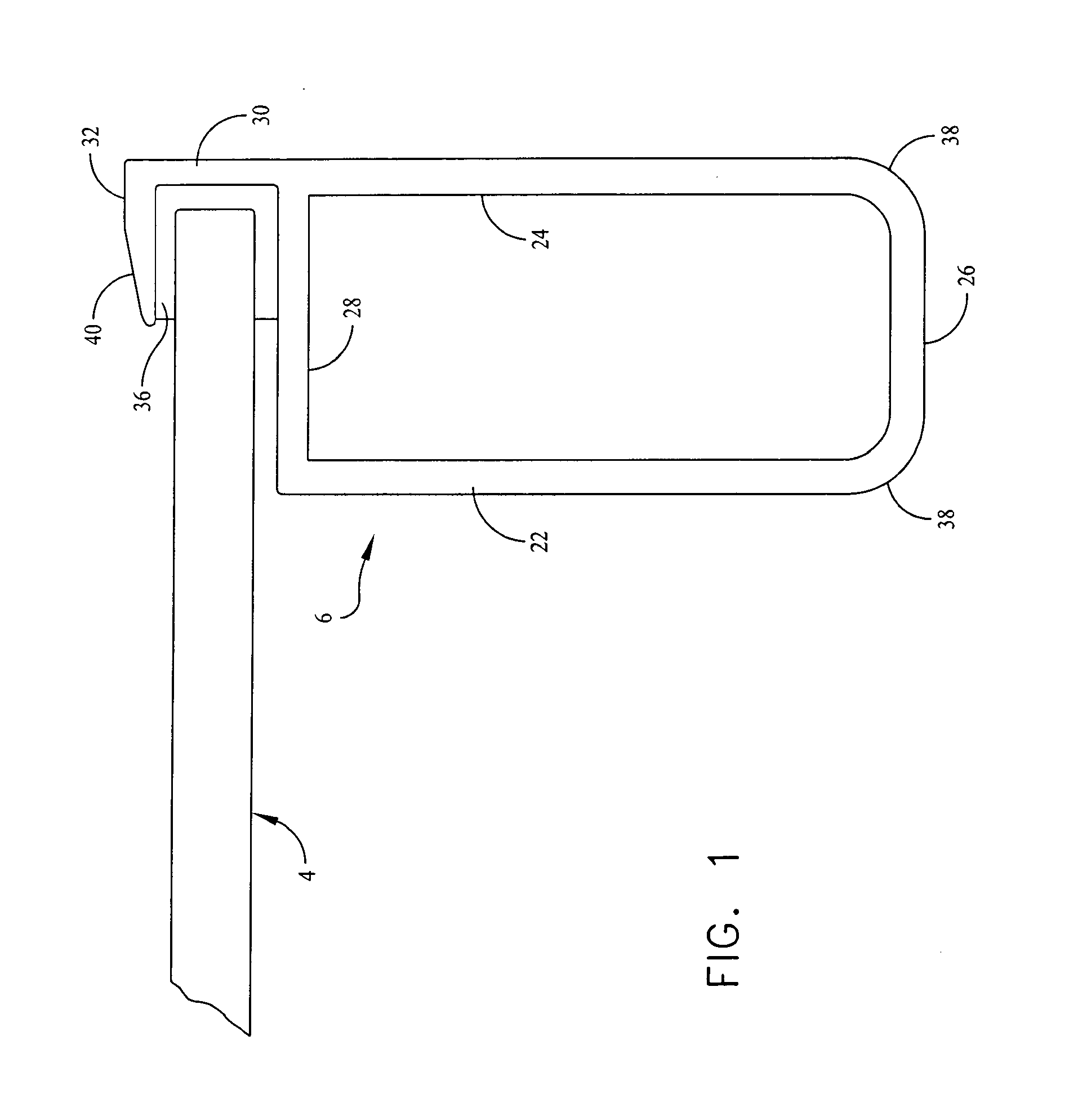
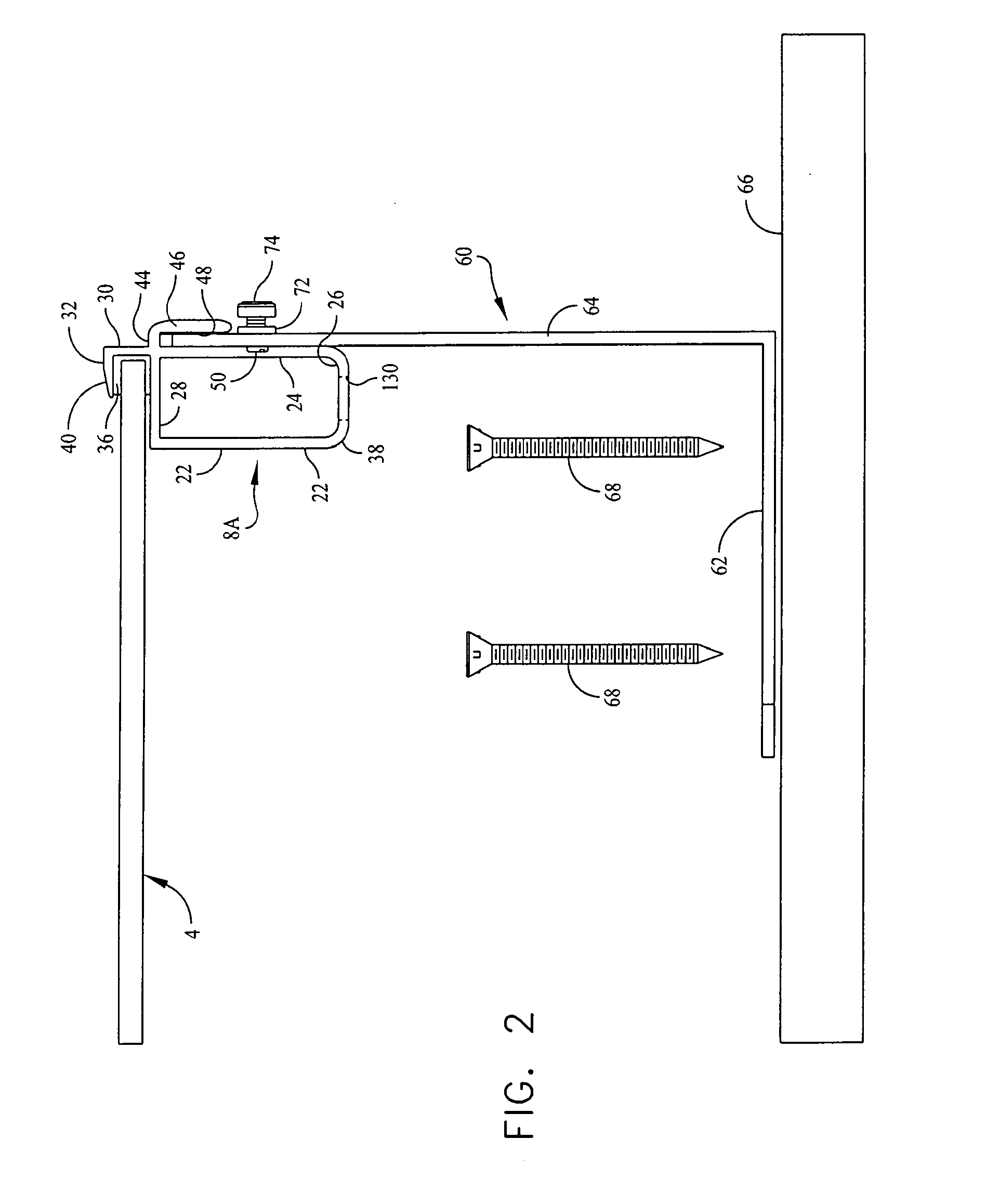
[0046]Referring now to FIGS. 1-4 and 6-8, there is shown a module that comprises one or more rectangular PV laminates 4 surrounded by a frame that comprises two opposite metal frame members 6 (FIGS. 1, 3, 4) and two opposite metal frame members 8A (FIGS. 2-4 and 6) and 8B (FIG. 7) that extend at a right angle ...


PUM


Abstract

PV modules are provided that have a frame construction which permits the photovoltaic power-generating cells, DC/AC power conversion means, electrical wiring and other installation aspects to be merged into the module. The modules also are provided with means for coupling them to mounting stands whereby they can be mounted to a roof and also the frame construction is adapted to facilitate mechanically securing adjacent modules to one another.

Description

FIELD OF INVENTION[0001]This invention relates generally to the manufacture and installation of photovoltaic power generating systems and in particular to a novel approach for using the frames of photovoltaic modules as a significant foundation for integrating those modules into a mounted photovoltaic power generating system. The invention also relates to AC photovoltaic modules and systems.BACKGROUND OF INVENTION[0002]The current state of the art of constructing and mounting photovoltaic (PV) modules, and also the integration of an array of such modules into an AC power generating system is evidenced by the disclosures of U.S. Pat. Nos. 5,460,660, issued Oct. 24, 1995 to S. P. Albright et al.; 6,750,391, issued Jun. 15, 2004 to W. I. Bower et al.; 6,959,517, issued Nov. 1, 2005 to J. J. Poddany et al.; 6,465,724, issued Oct. 15, 2002 to P. Garvison et al.; 6,046,399, issued Apr. 4, 2000 to M. Kapner; and 6,593,521, issued Jul. 15, 2003 to T. Kobayashi. The current state of the art ...

Claims


Application Information

Patent Timeline
Patent Type & Authority Applications(United States)
IPC IPC(8): H01L31/048
CPCF24J2/4614F24J2/5211F24J2/5254Y02B10/12Y02B10/14H02S40/34Y02E10/47Y02E10/50H02S20/00H02S40/32H02S20/23Y02B10/20F24S25/632F24S25/20F24S40/44Y02B10/10
Inventor KING, ZACHARY ADAMRUSSELL, MILES CLAYTONLITTLE, RUEL DAVENPORT
Owner GREENRAY
Why Eureka
Try Eureka