Machine conditioning monitoring closed loop lubrication system and method

a closed loop, lubrication technology, applied in the field of mechanical machine systems, can solve problems such as lubricant change that does not match actual lubricant wear and tear

Active Publication Date: 2010-06-17
ROCKWELL AUTOMATION TECH
View PDF13 Cites 32 Cited by
  • Summary
  • Abstract
  • Description
  • Claims
  • Application Information

AI Technical Summary

Problems solved by technology

These time dependent lubricant change intervals may not reflect the actual usage of a machine s...

Method used


Image

  • Machine conditioning monitoring closed loop lubrication system and method
  • Machine conditioning monitoring closed loop lubrication system and method
  • Machine conditioning monitoring closed loop lubrication system and method

Examples


Embodiment Construction

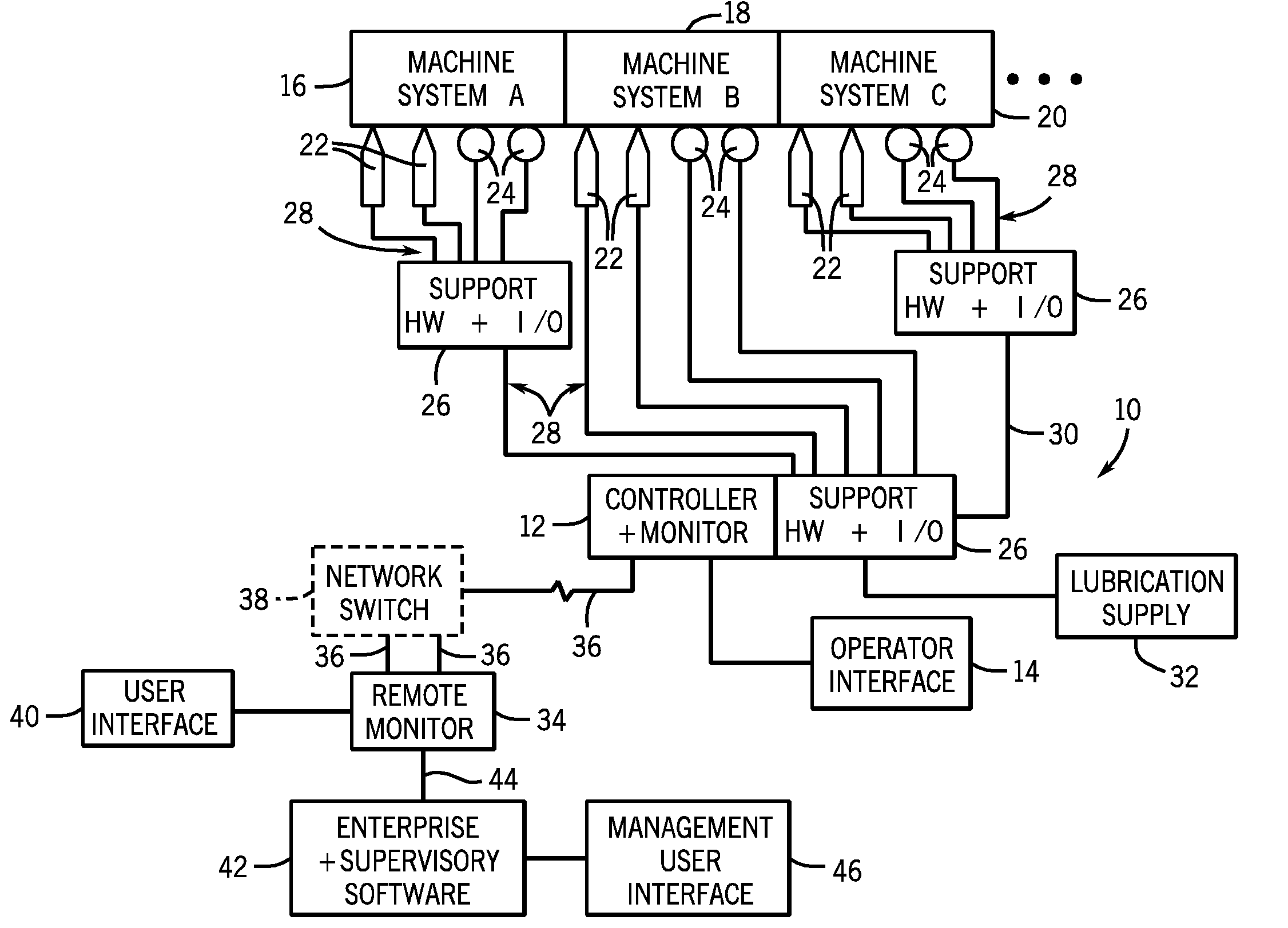
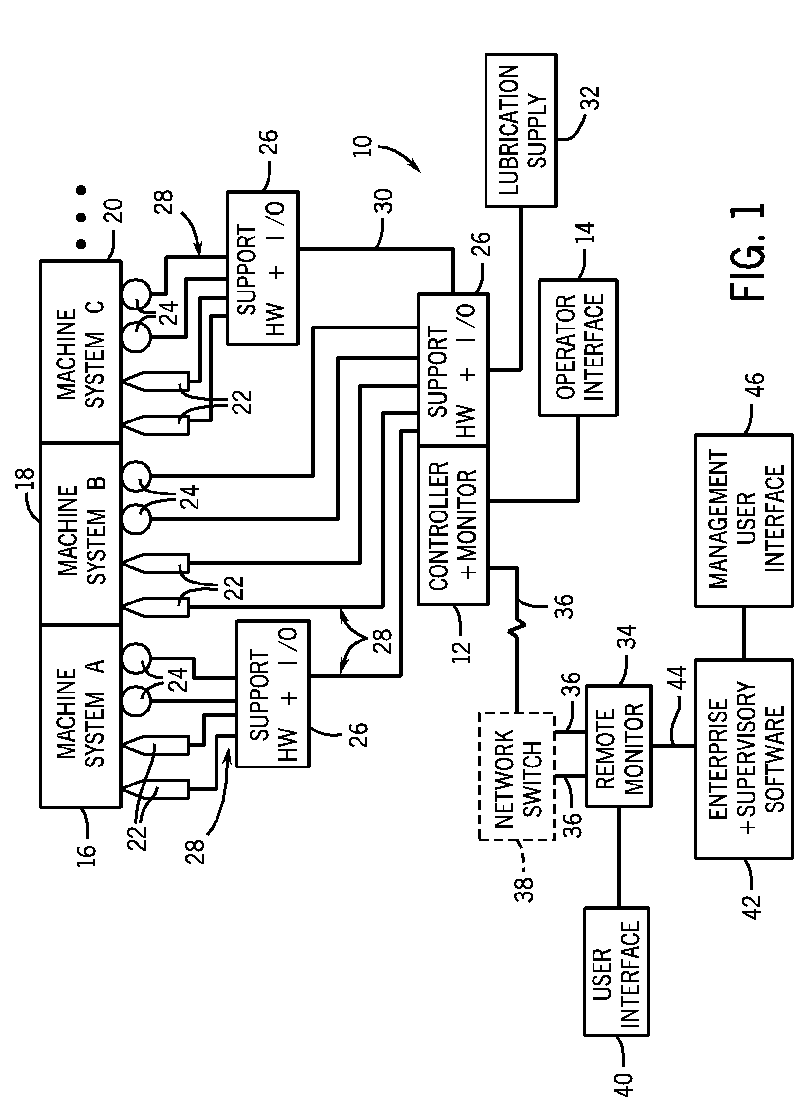
[0010]Turning now to the drawings, and referring first to FIG. 1, a diagrammatical overview of an embodiment of a machine condition monitoring and control system 10 is illustrated. The machine condition monitoring and control system 10 is particularly well suited for monitoring, detecting, and controlling a wide range of dynamic operating parameters of mechanical machine systems. In particular, the system is well suited to various types of rotary equipment, although other applications may be envisaged for certain aspects of the present technique. As referred herein, the term “dynamic operating condition” or the reference to condition monitoring is intended to convey physical conditions or parameters of a mechanical machine system, as opposed, for example, the electrical conditions. The dynamic conditions may include such characteristics as vibration, rotation, speed, temperature, pressure, and so forth.

[0011]The condition monitoring and control system 10 is designed to allow monitor...


PUM


Abstract

In one embodiment, the disclosed method for lubricating a machine bearing system includes monitoring a bearing system using a vibration sensor, such as an accelerometer, receiving a signal from the vibration sensor, calculating a parameter based on the signal; and adding a lubricant to the bearing system based upon the parameter. In another embodiment, a system may include a vibration sensor, a monitor configured to receive a signal from the vibration sensor and calculate a spike energy value, and a lubrication device configured to add a lubricant to a bearing system based on the spike energy value. The system and method help reduce maintenance and repair costs, while prolonging the life of the machine system components being monitored.

Description

BACKGROUND[0001]The invention relates generally to systems for monitoring of mechanical machine systems. More particularly, the invention relates to systems and methods for configuring, processing, and presenting machine condition monitoring information.[0002]Various systems and components may be used to monitor and protect industrial equipment and machines. Depending upon the type of mechanical system, the monitoring and protection components may generate various signals representative of dynamic conditions. The signal-generating components may be sensors and transducers positioned on points of interest of the machine systems. The signals are applied to monitoring circuits that are somewhat remote from the points of interest, and are used to analyze the performance of the machine system. Machine systems thus instrumented may include rotary machines, fansiblowers, pumps, assembly lines, production equipment, material handling equipment, power generation equipment, as well as many ot...

Claims


Application Information

Patent Timeline
IPC IPC(8): F16N29/00
CPCF16C33/6674F16N29/02G01H1/003F16N2250/38F16N2210/14
Inventor LAKOMIAK, JASON E.LOWE, PAUL A.LANTHIER, GILLESHEBEBRAND, MANDI L.
Owner ROCKWELL AUTOMATION TECH
Why Eureka
Try Eureka