Welded metal laminate structure and method for welding a metal laminate structure

Active Publication Date: 2010-06-17
MATERIAL SCIENCES CORPORATION
View PDF12 Cites 33 Cited by
  • Summary
  • Abstract
  • Description
  • Claims
  • Application Information

AI Technical Summary

Benefits of technology

[0007]In one aspect of this particular embodiment, a plug weld joint is formed. In this instance, the method also includes creating one or more plug holes in one of the work pieces prior to welding. The metal cored wire electrode is then melted into each plug hole. In order to form the weld joint, the welding gun is first moved in a circular motion around the perimeter of each plug hole, applying the melted metal cored wire

Problems solved by technology

The higher weld current results in increased weld porosity and melt through, both of which are undesirable welding defects.
Using

Method used


Image

  • Welded metal laminate structure and method for welding a metal laminate structure
  • Welded metal laminate structure and method for welding a metal laminate structure
  • Welded metal laminate structure and method for welding a metal laminate structure

Examples


Embodiment Construction

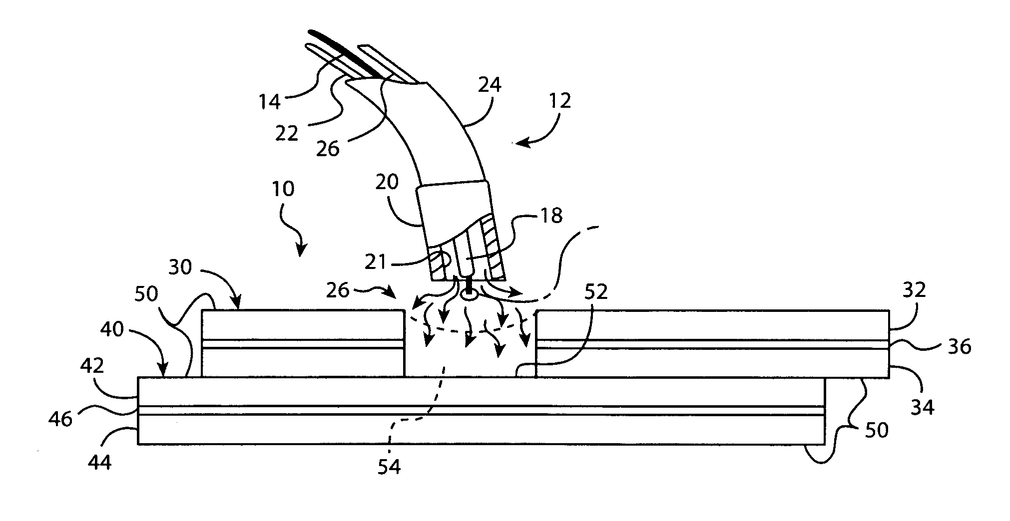
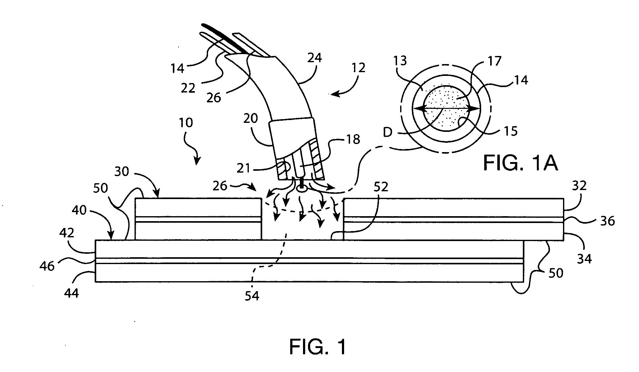
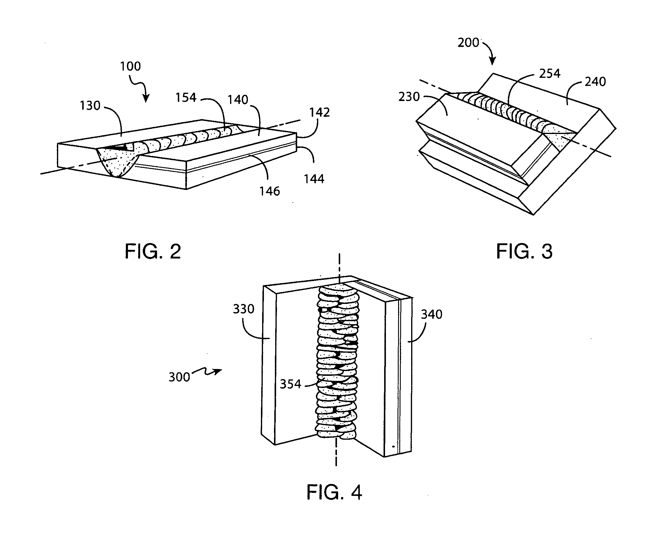
[0022]Referring to the drawing, wherein like reference numbers refer to like elements throughout the several views, FIG. 1 schematically illustrates a representative welded metal structure, designated generally by reference numeral 10, in accordance with the present invention. The various embodiments of the present invention are described herein with respect to the welded metal structures illustrated throughout the drawings, which are provided purely for explanatory purposes. It should therefore be readily understood that the present invention is by no means limited to the arrangements presented in FIGS. 1-4. In addition, the drawings presented herein are not to scale, and are provided purely for instructional purposes. Thus, the individual and relative dimensions and orientations shown in the drawings are not to be considered limiting.

[0023]FIG. 1 schematically illustrates an exemplary welding gun, indicated generally at 12, for practicing the methods and creating the various welde...


PUM

PropertyMeasurementUnit
Timeaaaaaaaaaa
Timeaaaaaaaaaa
Fractionaaaaaaaaaa

Abstract

An improved method for welding a laminated metal structure is presented herein. In one embodiment, the method includes: placing the laminated structure against a second work piece, feeding a consumable metal cored wire electrode to the weld zone, feeding a stream of shielding gas to the weld zone, and melting the consumable metal cored wire electrode. If the weld joint is a plug weld, the method also includes forming a plug hole in one of the work pieces, melting the consumable metal cored wire electrode along the circumference of the plug hole, and thereafter progressively spiraling the welding gun inwards towards the center of the plug hole to fill it with the melted electrode. The method may also include determining if melting the electrode is causing sputtering, and delaying spiraling the welding gun inwards until the sputtering subsides. A welded laminate metal structure is also provided herein.

Description

TECHNICAL FIELD[0001]The present invention relates generally to laminated metal structures, and more specifically to welded metal-polymer-metal laminate structures, and methods of welding metal-polymer-metal laminates to other metal or metal laminate structures.BACKGROUND OF THE INVENTION[0002]In various industries, metal laminate structures comprising a polymeric core sandwiched between two metallic layers are used to manufacture a variety of different products. An example of such metal-polymer-metal laminates includes a constrained layer damper for the prevention and attenuation of vibration. Most constrained layer dampers, or “CLD” for short, include a very thin layer of a vibration-absorbing viscoelastic material that is disposed between and adhered to two metal-panel constraining layers. Constrained layer dampers are used in the automotive industry for vehicle body panels as well as damping inserts for automobile brake systems to diminish the propagation of structure-borne nois...

Claims


Application Information

Patent Timeline
IPC IPC(8): B23K9/00
CPCB23K2203/16B23K9/0026B23K2103/16B23K2103/172
Inventor FONDRIEST, DANIEL
Owner MATERIAL SCIENCES CORPORATION
Why Eureka
Try Eureka