

Cutting Tool and Cutting Insert Therefor
a cutting tool and cutting insert technology, applied in metal-working equipment, metal-working equipment, milling equipment, etc., can solve the problems of reducing the performance of cutting tools, reducing the service life of cutting tools, so as to achieve high resistance to exertion
- Summary
- Abstract
- Description
- Claims
- Application Information
AI Technical Summary
Benefits of technology
Problems solved by technology
Method used
Image

Examples
Embodiment Construction
[0030]In the following description, various aspects of the present invention will be described. For purposes of explanation, specific configurations and details are set forth in order to provide a thorough understanding of the present invention. However, it will also be apparent to one skilled in the art that the present invention may be practiced without the specific details presented herein. Furthermore, well-known features may be omitted or simplified in order not to obscure the present invention.
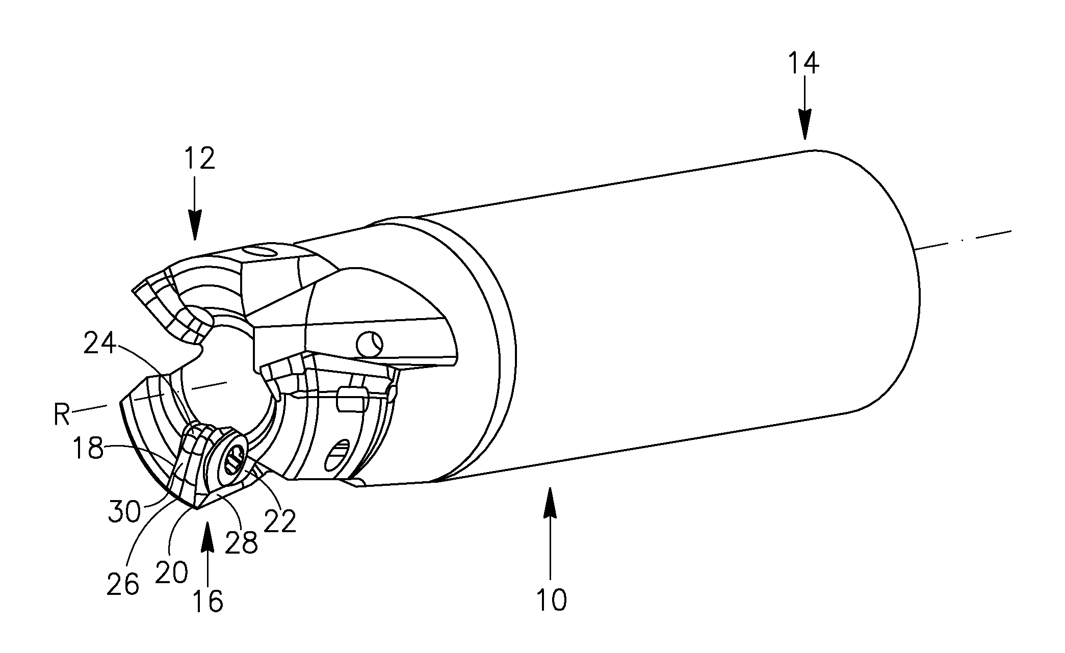
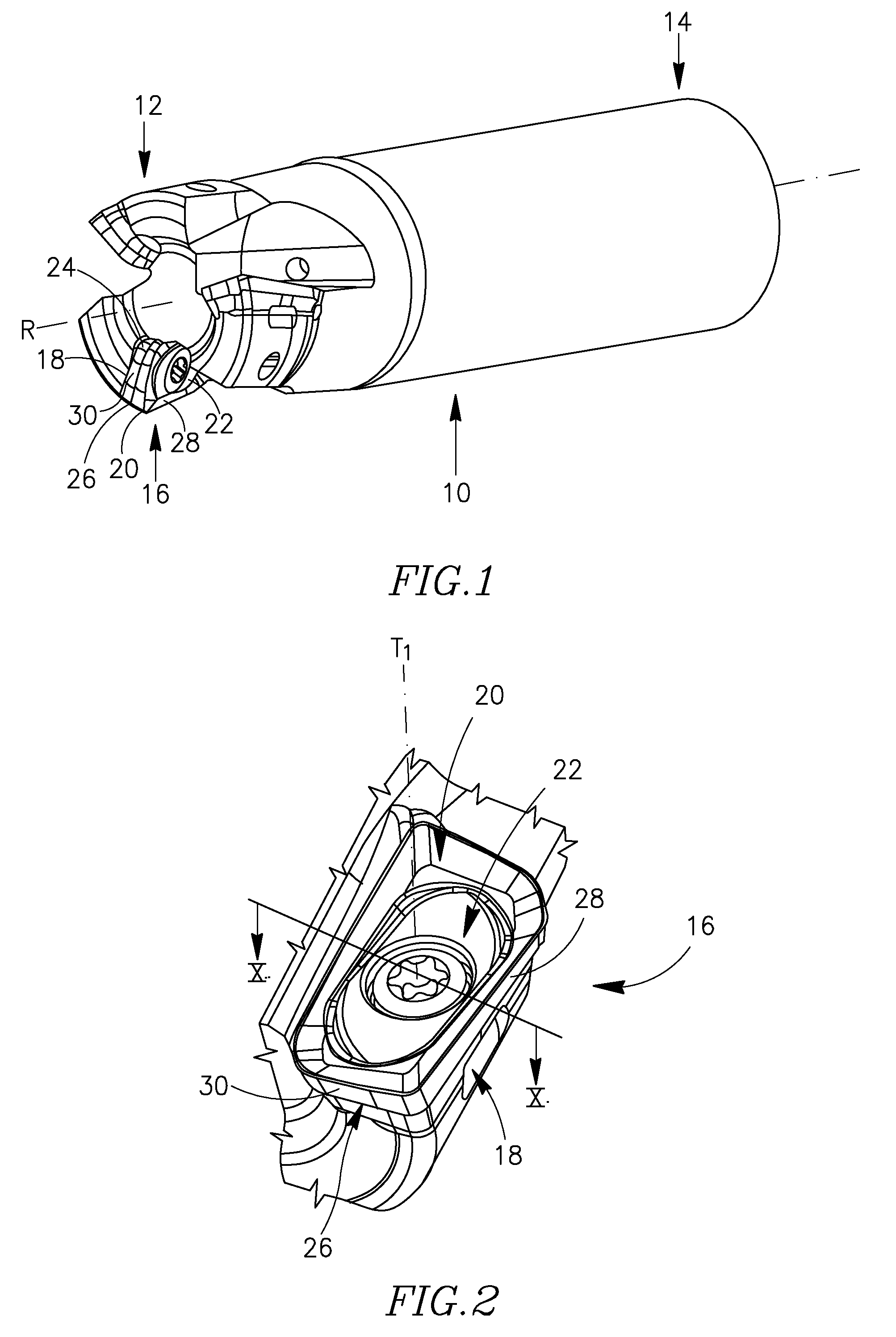
[0031]Although some drawings herein show, and / or some descriptions herein refer to a rotating cutting tool such as a milling tool, the present invention is not limited in this respect. For example, some embodiments of the invention may refer to a plurality of other cutting tools e.g., to various other rotating tools such as drilling tools, reaming tools or the like, or to turning tools, or to any other metal cutting tool that include one or more releasably retained cutting inserts.
[0032]...
PUM
| Property | Measurement | Unit |
|---|---|---|
| obtuse angle | aaaaa | aaaaa |
| obtuse angle | aaaaa | aaaaa |
| acute angle | aaaaa | aaaaa |
Abstract
Description
Claims
Application Information