
Outer sole and shoes

a technology of outer soles and shoes, applied in the field of outer soles of shoes and shoes, can solve the problems of inferior abrasion resistance of the outer sole of patent document 1, insufficient abrasion resistance of the grounding layer, and inferior abrasion resistance of the outer sole of the patent document 1, and achieve excellent abrasion resistan

Inactive Publication Date: 2010-06-24
ASICS CORP
View PDF5 Cites 41 Cited by
  • Summary
  • Abstract
  • Description
  • Claims
  • Application Information

AI Technical Summary

Benefits of technology

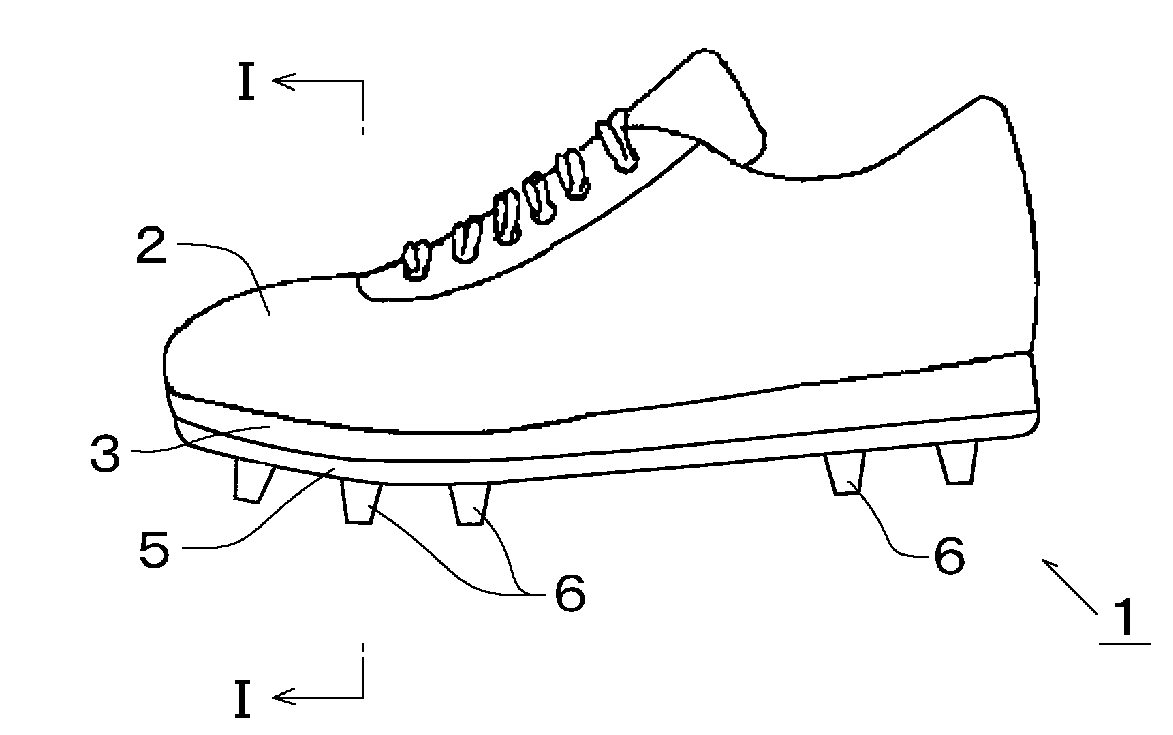
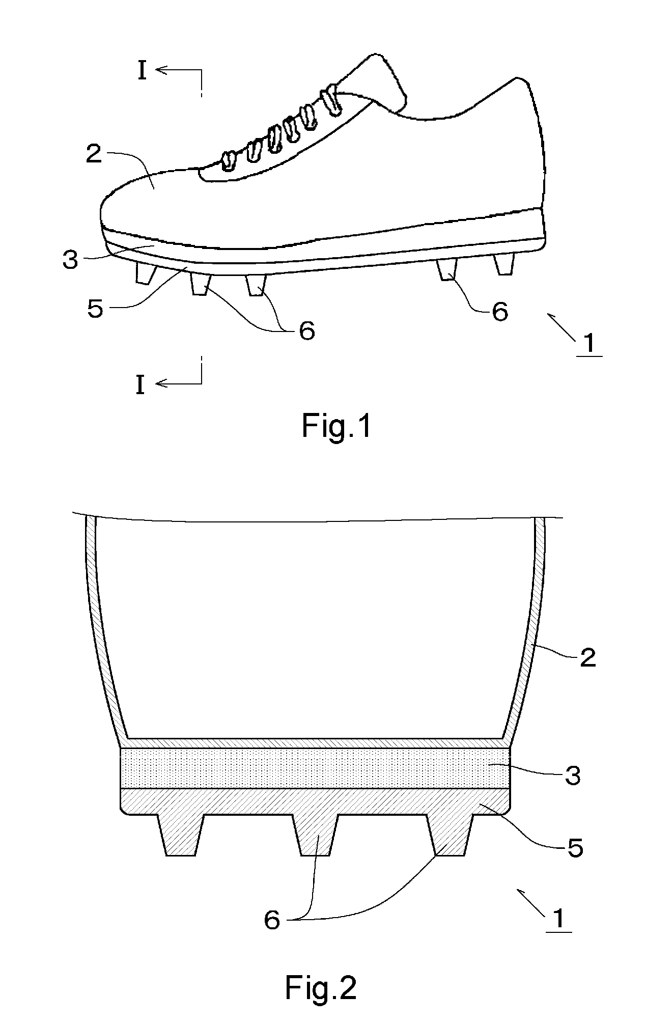
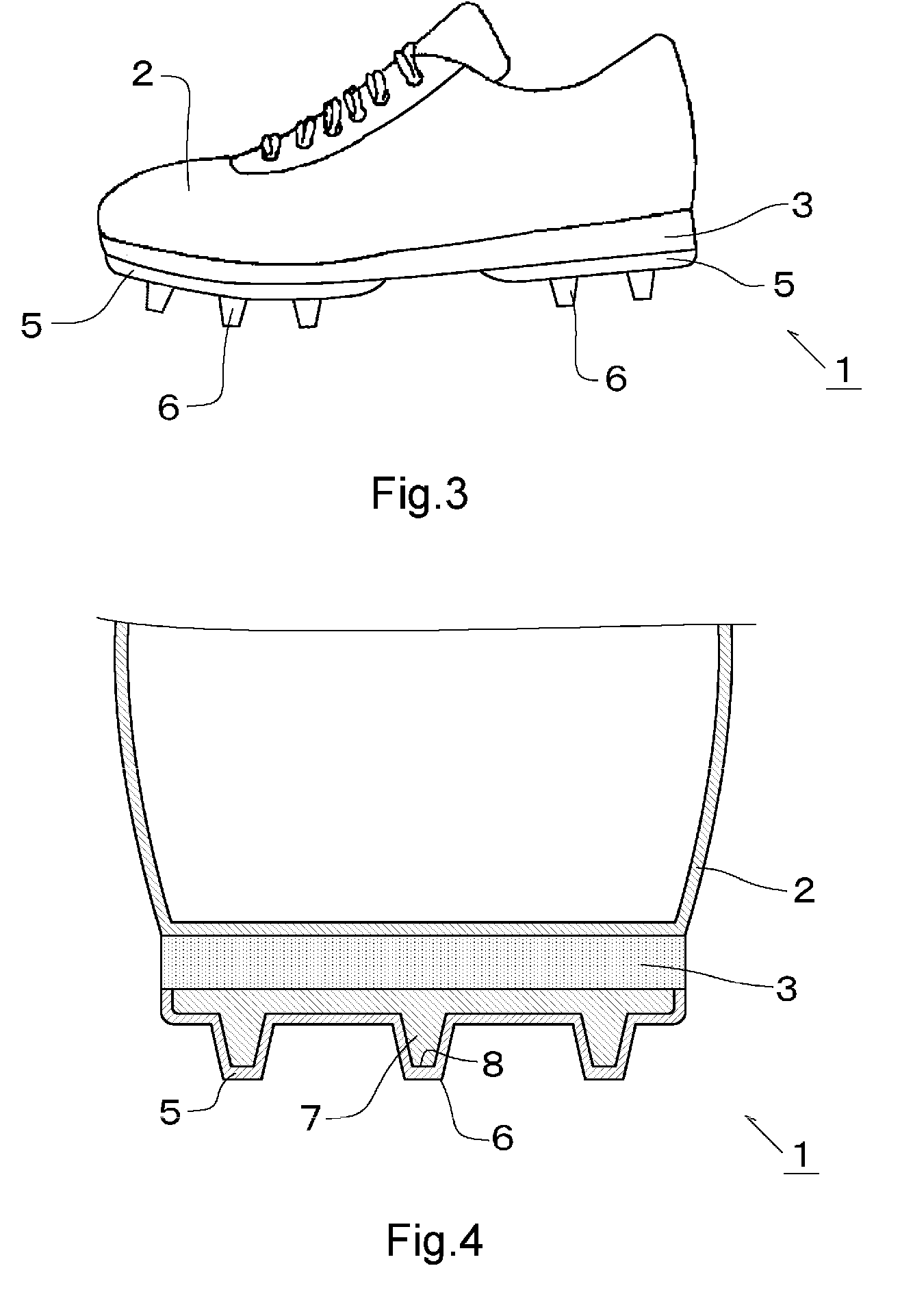
The present invention provides an outer sole that is lightweight and has good abrasion resistance. The outer sole is made from a polymer composition with a specific gravity of 0.95 or less, which contains an olefin resin and a styrene elastomer. The outer sole has a storage elastic modulus of 100 MPa to 500 MPa and a maximum tensile stress of 30 MPa or more. The outer sole is formed out of a polymer composition with a specific gravity of 0.95 or less, which allows for easy absorption of shock and restoration to the original shape after deformation. The outer sole is also designed to decrease the occurrence of flaws and prevent lamps from falling off. The patent text also describes shoes with the outer sole.

Problems solved by technology

However, the outer sole of Patent Document 1 is inferior in abrasion resistance in a region with a foam arranged by reason of using a foam.
However, sufficient abrasion resistance of the grounding layer is not obtained only by comparatively increasing the hardness of the grounding layer and the grounding layer is requested to be improved.
Generally, materials comparatively small in specific gravities are excellent in weight reduction but inferior in abrasion resistance, while materials excellent in abrasion resistance tend to be comparatively large in specific gravities.

Method used


Image

  • Outer sole and shoes
  • Outer sole and shoes
  • Outer sole and shoes

Examples


example 1

[0094]PE, PP, and aSBS were blended at the ratio shown in Table 1, sufficiently mixed by a mixer and thereafter kneaded by a twin-screw extruder (180 to 230° C.) to prepare a polymer composition. The specific gravity of the polymer composition (20° C.±3° C.) is as shown in Table 1. In Table 1, the blending ratio of each material is denoted as part by mass.

[0095]The above-mentioned polymer composition was injected into a metallic mold by using an injection molding machine (maker: manufactured by Nissei Resin Industry Co., product name: FE160S type hydraulic injection molding machine, clamping force: 160 ton, screw diameter: 45 mm, injection speed: 21 cm3 / s, injection pressure: 60 MPa: injection temperature (nozzle portion): 230° C.) to produce a sample for physical tests and a sample for abrasion tests.

[0096]The above-mentioned sample for physical tests was used for the measurement of specific gravity, the measurement of dynamic viscoelasticity, and the measurement of tensile strengt...

examples 2 to 5

[0098]A sample for physical tests and a sample for abrasion tests were produced in the same manner as the above-mentioned Example 1 except for blending PE, PP, and aSBS at the ratio shown in Table 1. The specific gravity of each polymer composition (20° C.±3° C.) of Examples 2 to 5 is as shown in Table 1.


PUM

PropertyMeasurementUnit
specific gravityaaaaaaaaaa
tensile stressaaaaaaaaaa

Abstract

The present invention provides an outer sole light in weight and excellent in abrasion resistance.The outer sole of the present invention is formed out of a polymer composition with a specific gravity of 0.95 or less, which contains an olefin resin and a styrene elastomer, wherein a storage elastic modulus [E′] and a loss coefficient [tan δ] in a dynamic viscoelasticity measurement (20±3° C., 10 Hz) are 100 MPa to 500 MPa and 0.2 or less respectively, and a maximum tensile stress is 30 MPa or more. The olefin resin contains an ethylene polymer and a propylene polymer, for example. The styrene elastomer contains an α-methyl styrene.butadiene copolymer, for example.A flaw is hardly occurred on the outer sole in use, so that the outer sole is excellent in abrasion resistance.

Description

TECHNICAL FIELD[0001]The present invention relates to an outer sole of shoes and shoes.BACKGROUND ART[0002]An outer sole in shoes of various kinds such as sports shoes is a bottom member contacting with the ground. The outer sole is requested to be resistant to abrasion (abrasion resistance) and light in weight.[0003]Patent Document 1 (Japanese Unexamined Patent Publication No. 11-266905) describes an outer sole into which a light-weight foam with a specific gravity of 0.8 or less and a high-strength nonfoam are butted and integrally joined. It is described in Patent Document 1 that such an outer sole is excellent in abrasion resistance and light in weight for the reason that a high-strength nonfoam is arranged in a region requiring abrasion resistance and a light-weight foam is arranged in the other region.[0004]Patent Document 2 (Japanese Unexamined Patent Publication No. 2007-29320) discloses an outer sole having a laminated part such that a grounding layer with a Shore A hardnes...

Claims


Application Information

Patent Timeline
Patent Type & Authority Applications(United States)
IPC IPC(8): A43B5/00A43B13/14A43C15/00
CPCA43B13/04A43B13/187C08L53/02C08L23/10C08L23/04A43B13/26A43B13/189C08L23/06C08L23/12
Inventor IMAZATO, KATSUHIROMORI, SADAKI
Owner ASICS CORP
Learn More