Combined wafer area pressure control and plasma confinement assembly

a pressure control and plasma technology, applied in the direction of coatings, waveguide type devices, chemical vapor deposition coatings, etc., can solve the problems of affecting the surface of the confinement ring is relatively inefficient, and the deposition quantity is left on the surface of the confinement ring to achieve the effect of facilitating the processing of the substra

Active Publication Date: 2010-06-24
LAM RES CORP
View PDF13 Cites 21 Cited by
  • Summary
  • Abstract
  • Description
  • Claims
  • Application Information

AI Technical Summary

Benefits of technology

[0012]The invention relates, in an embodiment, to a combined pressure control/plasma confinement assembly configured for confining a plasma and for at least partially regulating pressure in a plasma processing chamber during plasma processing of a substrate. The assembly includes a movable plasma confinement structure having therein a plurality of perforations and configured to surround the plasma when deployed. The assembly also includes a movable pressure control structure disposed outside of the movable plasma confinement s...

Problems solved by technology

Since the energy of ions accelerated from the plasma is governed by the sheath potential, a low sheath potential results in a low energy level of ion bombardment on the surfaces of the confinement rings.
Consequently, film removal processes such as sputtering and ion-enhanced etching (such as those occurring during in-situ plasma clean processes) are relatively ...

Method used


Image

  • Combined wafer area pressure control and plasma confinement assembly
  • Combined wafer area pressure control and plasma confinement assembly
  • Combined wafer area pressure control and plasma confinement assembly

Examples


Embodiment Construction

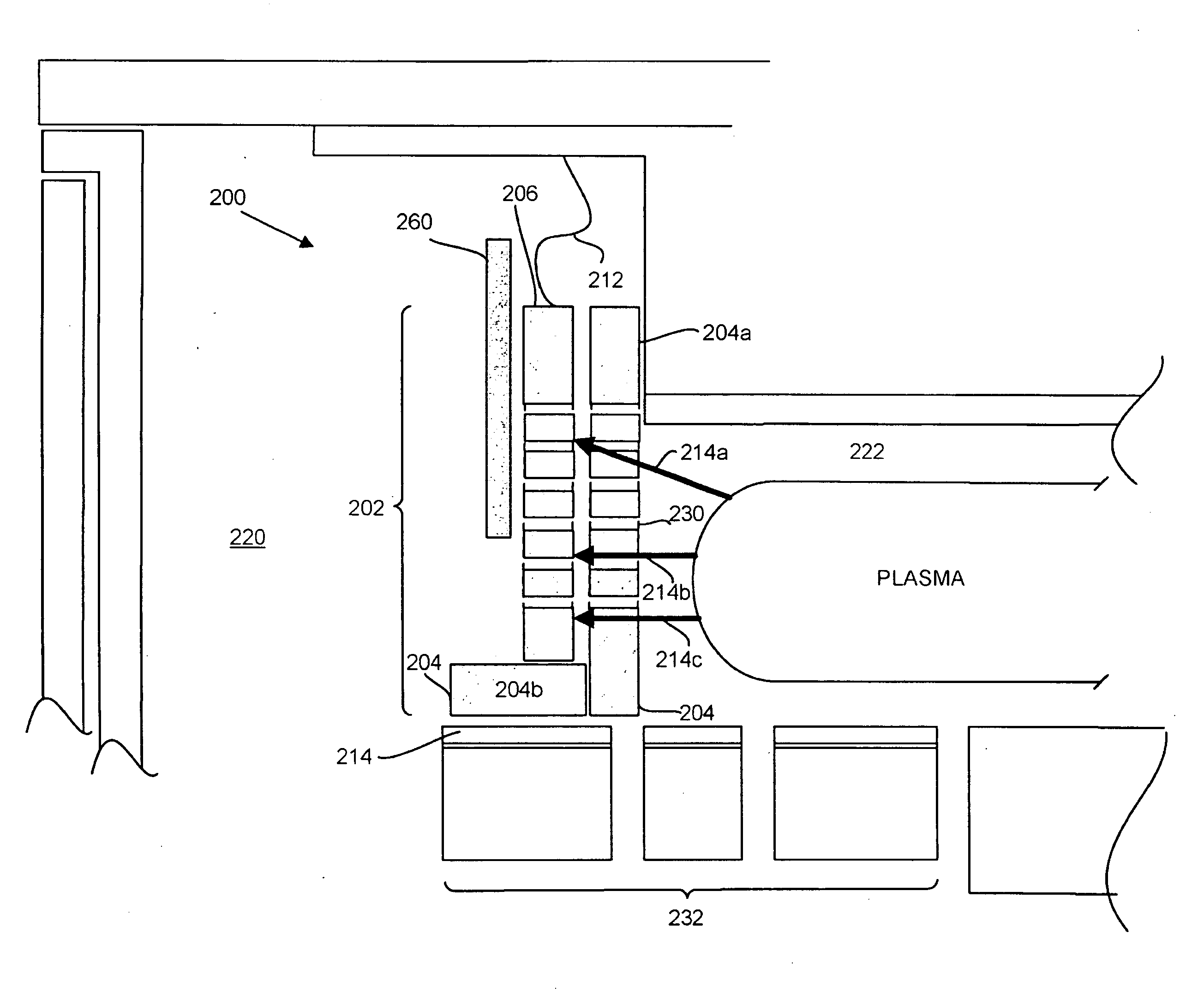
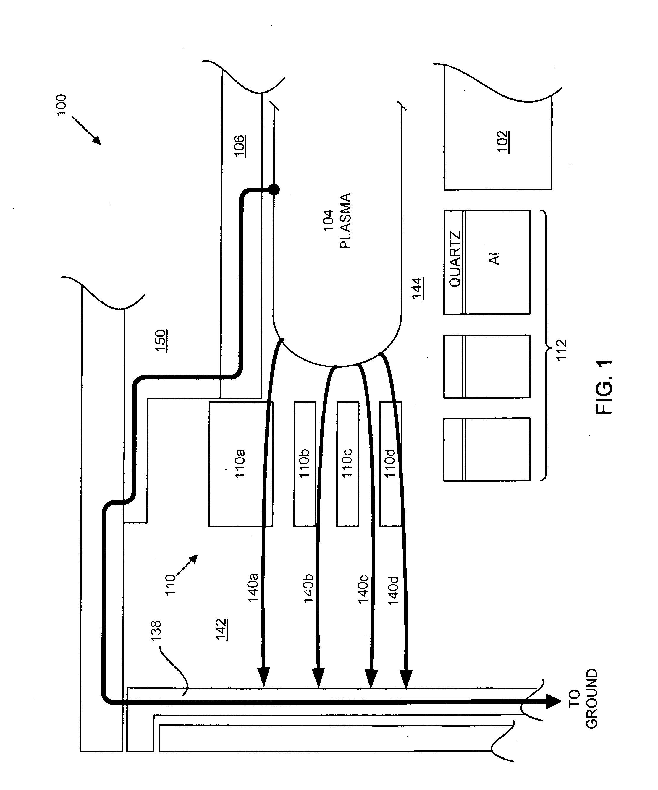
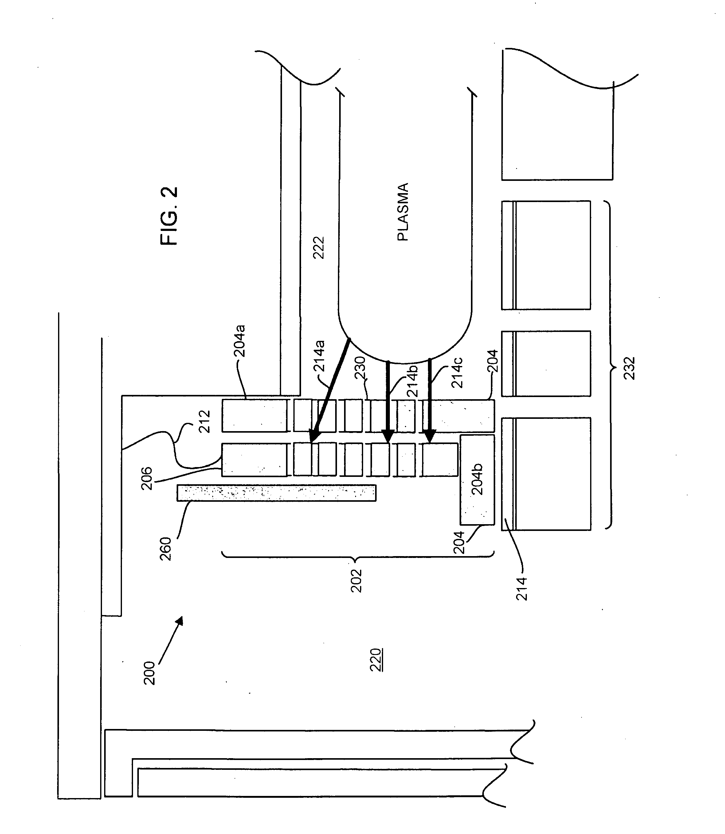
[0020]The present invention will now be described in detail with reference to a few embodiments thereof as illustrated in the accompanying drawings. In the following description, numerous specific details are set forth in order to provide a thorough understanding of the present invention. It will be apparent, however, to one skilled in the art, that the present invention may be practiced without some or all of these specific details. In other instances, well known process steps and / or structures have not been described in detail in order to not unnecessarily obscure the present invention.

[0021]Generally speaking, one or more embodiments of the invention relate to improved methods and arrangements for processing substrates in a plasma processing chamber while reducing residue accumulation on the confinement rings and / or structures that face the plasma. In one or more embodiments, the improvement also helps keep the plasma confined in the plasma confinement region, i.e., reducing the ...


PUM

PropertyMeasurementUnit
Pressureaaaaaaaaaa
Electrical conductivityaaaaaaaaaa
Electrical conductoraaaaaaaaaa

Abstract

A combined pressure control/plasma confinement assembly configured for confining a plasma and for at least partially regulating pressure in a plasma processing chamber during plasma processing of a substrate is provided. The assembly includes a movable plasma confinement structure having therein a plurality of perforations and configured to surround the plasma when deployed. The assembly also includes a movable pressure control structure disposed outside of the movable plasma confinement structure such that the movable plasma confinement structure is disposed between the plasma and the movable pressure control structure during the plasma processing, the movable pressure control structure being deployable and retractable along with the movable plasma confinement structure to facilitate handling of the substrate, the movable pressure control structure being independently movable relative to the movable plasma confinement structure to regulate the pressure by blocking at least a portion of the plurality of perforations.

Description

PRIORITY CLAIM[0001]This application is related to and claims priority under 35 U.S.C. §119(e) to a commonly assigned provisional patent application entitled “COMBINED WAFER AREA PRESSURE CONTROL AND PLASMA CONFINEMENT ASSEMBLY,” by Fischer et al., Attorney Docket Number P1863P / LMRX-P 171P, Application Ser. No. 61 / 139,496 filed on Dec. 19, 2008, all of which are incorporated herein by reference.BACKGROUND OF THE INVENTION[0002]Plasma processing systems have long been employed to process substrates (e.g., wafers) in plasma processing systems. In a typical plasma processing chamber, plasma is ignited and confined in a plasma confinement region, which is typically defined by the chamber upper and lower strictures, as well as by structures that annularly surround the plasma confinement region.[0003]To facilitate the insertion and removal of substrates, as well as to facilitate the evacuation of exhaust gas from the plasma processing chamber, many chambers employ a set of movable confine...

Claims


Application Information

Patent Timeline
IPC IPC(8): C23C16/44H01P11/00
CPCH01J37/32449Y10T29/49016H01J37/32642H01J37/32623
Inventor FISCHERKOSHIISHI, AKIRA
Owner LAM RES CORP
Why Eureka
Try Eureka