Encapsulated RGB oleds having enhanced optical output

a technology of encapsulated rgb and optical output, which is applied in the direction of discharge tube/lamp details, discharge tube luminescnet screens, organic semiconductor devices, etc., can solve the problems of not necessarily achieving optimized light output, and affecting the efficiency of rgb applications

Active Publication Date: 2010-06-24
SAMSUNG DISPLAY CO LTD
View PDF103 Cites 18 Cited by
  • Summary
  • Abstract
  • Description
  • Claims
  • Application Information

AI Technical Summary

Problems solved by technology

Currently, this efficiency is only about 20-25%, due to the planar waveguiding properties of the OLED device.
However, these methods do not necessarily result in optimized light output.
The structure in a quarter wave stack is wavelength dependent, which means that the use of the same structure for RGB applications can be problematic.
Also, the number of layers needed for an effective quarter wave (QW) stack can be quite high (e.g., 10 layers pairs), which makes it impractical for many commercial applications.
Another disadvantage of the structure is that the intensity of the light transmitted by a QW stack is strongly directional, and in general the stack is designed with maximum intensity for forward transmission.
This feature is generally unfavorable for display applications because it limits the viewing angle and is unacceptable for general applications in solid state lighting (SSL).
It would become impractical for thick layers (100 nm
The implementation is therefore practically difficult and complex and may require a different sequence of layers as well as different thicknesses of the layers in parts of the device.
Another problem with using OLEDs in flat panel displays and other information display formats is that they are limited by the poor environmental stability of the devices. G. Gustafson, Y. Cao, G. M. Treacy, F. Klavetter, N. Colaneri, and A. J. Heeger, Nature, Vol. 35, 11 Jun. 1992, pages 477-479.
Humidity and oxygen significantly reduce the useful life of most OLEDs.

Method used


Image

  • Encapsulated RGB oleds having enhanced optical output
  • Encapsulated RGB oleds having enhanced optical output
  • Encapsulated RGB oleds having enhanced optical output

Examples


example 1

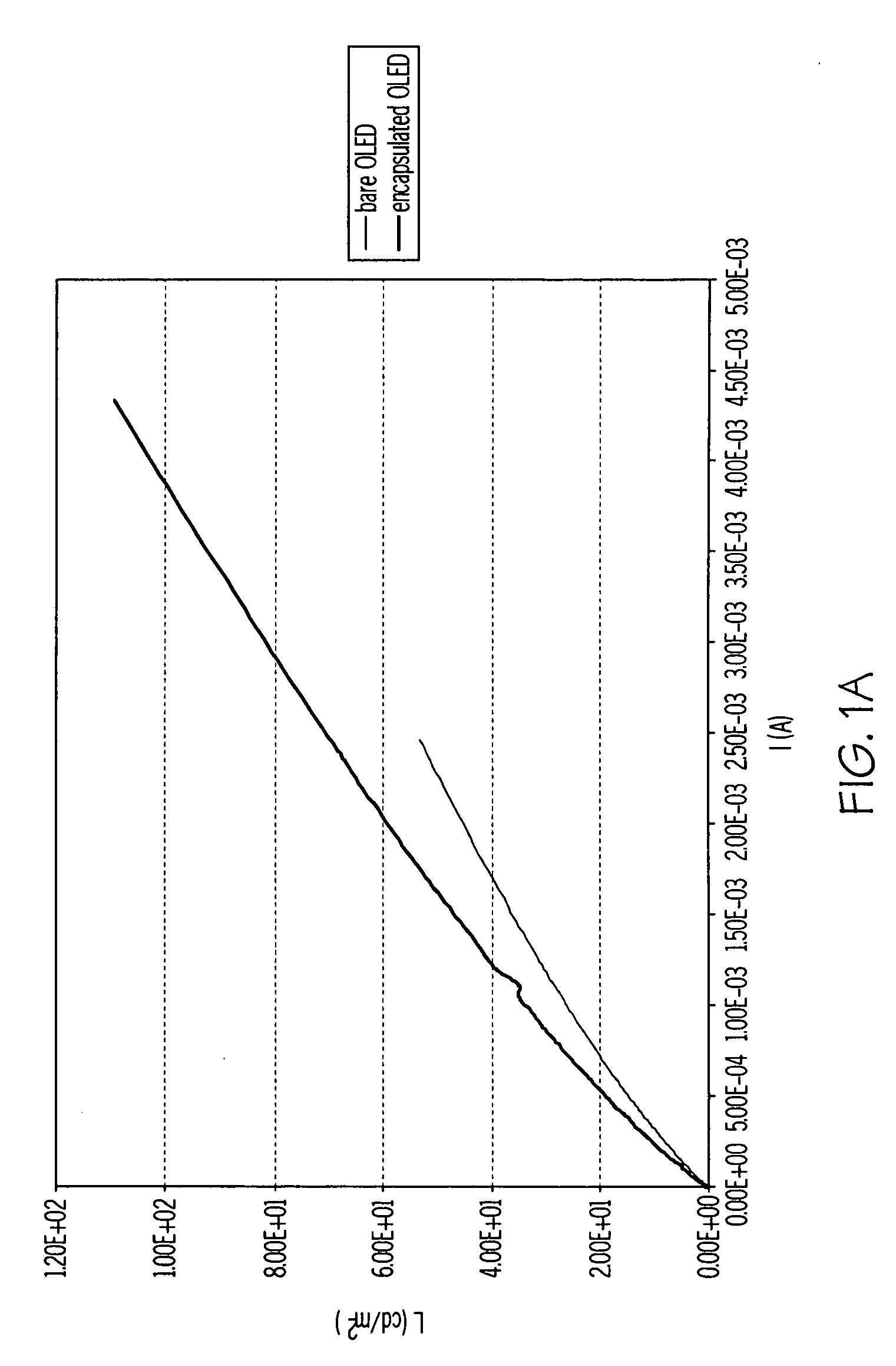
[0063]FIG. 1A compares the experimentally observed light emission of a bare OLED and of the same OLED after coating with an integrated barrier and optical enhancement stack. The integrated barrier and optical enhancement stack included a 50 nm LiF plasma protective layer (RI-1.395), a 100 nm aluminum oxide barrier layer (RI-1.65), and 4 barrier stacks of 0.5 μm acrylate polymer (RI-1.5) and 35 nm aluminum oxide (RI-1.65). The graph shows the experimental I-L curves for the OLEDs. The I-L curve for an OLED is obtained by measuring the light emitted by the OLED device as a function of the current used for driving the device itself. The light was measured in the forward direction. FIG. 1A shows an enhancement of 25% for the encapsulated OLED.

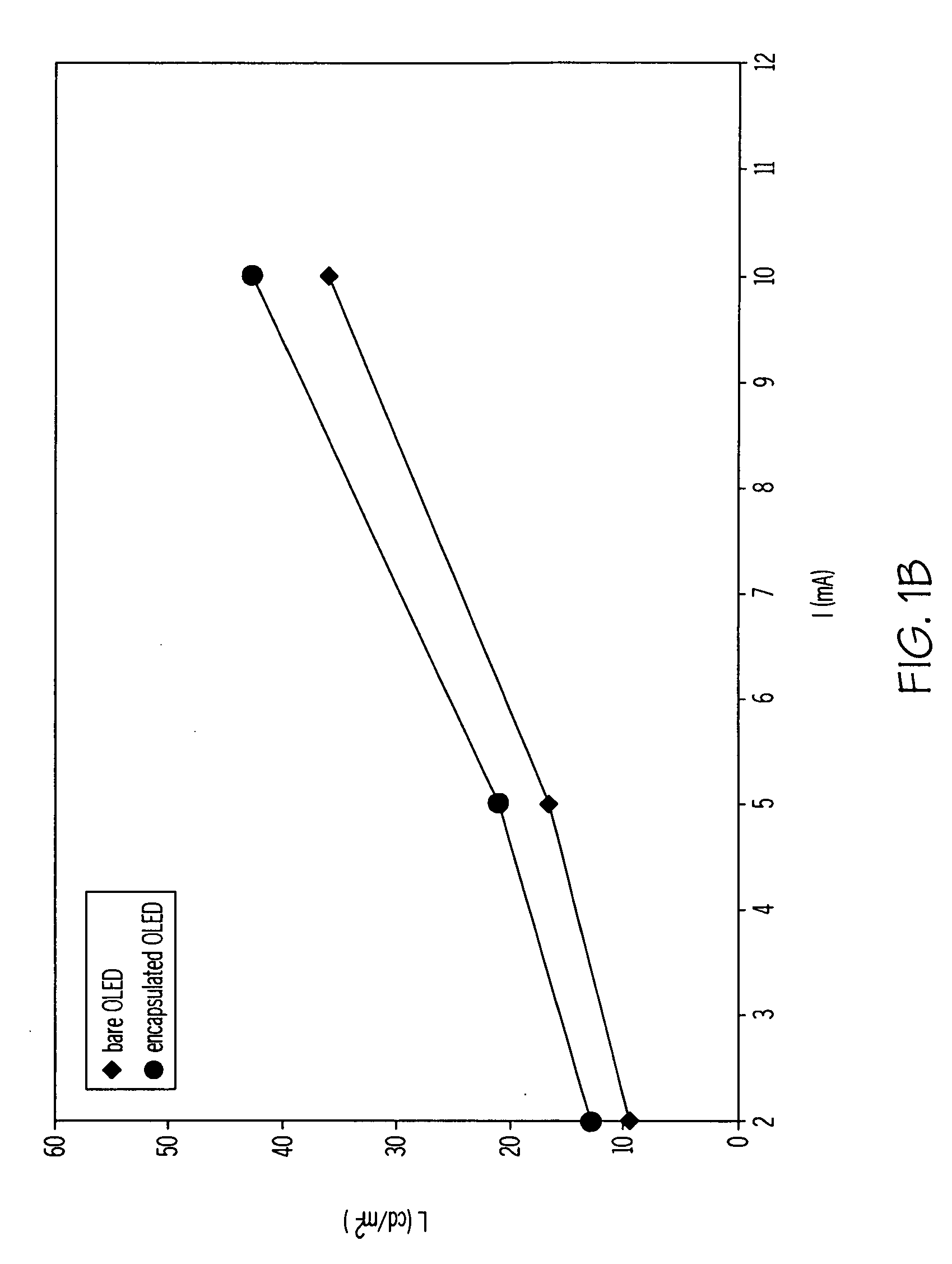
[0064]FIG. 1B compares the experimentally observed light emission of a second bare OLED and the same OLED after encapsulation. The integrated barrier and optical enhancement stack included a 50 nm LiF plasma protective layer (RI-1.395), a 100 nm al...

example 2

[0066]The effect of inorganic plasma protective layers and inorganic barrier layers between the OLED and the barrier stack were evaluated using the simulation. The OLED has a 250 nm thick ITO cathode. Three barrier stacks are included, each having a 1 μm polymeric decoupling layer and a 40 nm inorganic oxide barrier layer with a 1 μm polymeric decoupling layer on top of the barrier stacks. The light output of a bare OLED with a 250 nm ITO cathode was compared with encapsulated OLEDs having an inorganic plasma protective layer and different thicknesses of initial inorganic barrier layers (50 nm LiF / 120 nm aluminum oxide; 120 nm aluminum oxide; 50 nm LiF / 40 nm aluminum oxide), as shown in FIG. 2. The encapsulated OLED with the LiF inorganic plasma protective layer and 120 nm initial inorganic oxide barrier layer provided improved light output. The optimization was in terms of peak intensity, color purity, and color coordinates. The model shows that the introduction of the plasma prote...

example 3

[0067]Example 3 shows experimental results of the effect of introducing a plasma protective layer.

[0068]FIG. 3 compares the effect of different protective layers having the same thickness. The graphs report experimental I-L curves. The emitted light was measured in the forward direction. The two OLEDs had the identical structure and had been deposited on the same motherglass (in the same run). The two protective layers, PL1 and PL2, had the same thickness, 50 nm. The RI of PL1 was 1.4, and the RI of PL2 was 1.8. FIG. 3A shows an enhancement of 35% for the PPL with an RI of 1.4, while FIG. 3B shows an enhancement of 14% for a PPL with the RI of 1.8.


PUM


Abstract

Methods of making an integrated barrier stack and optical enhancement layer for protecting and improving the light out coupling of an encapsulated OLED are described. The method includes optimizing the thickness of various layers including the initial inorganic barrier layer and the inorganic barrier layer and polymeric decoupling layer for the barrier stack. The thickness is optimized for at least one of maximum efficiency, minimum dispersion, or minimum spectral shift so that the encapsulated OLED has enhanced light outcoupling compared to the bare OLED.

Description

[0001]The invention relates generally to encapsulated organic light emitting devices (OLEDs), and more particularly to encapsulated red, green, and blue (RGB) OLEDs having improved light outcoupling compared to the bare RGB OLED.BACKGROUND OF THE INVENTION[0002]The optimization of the light outcoupling from an OLED is an important factor in the commercialization of OLEDs in many applications.[0003]OLEDs have reached remarkable levels of power efficiencies over the years by lowering the operating voltage and increasing the quantum yield of internal light generation to almost 100% resulting in power efficiencies of more than 120 Lm / Watt for green light (Ultra High Efficiency Green Organic Light-Emitting Devices, Jpn. J. Appl. Phys. 46, p. L10-L12, (2007))|and recently 100 Lm / W for white light (Press Release of Jun. 17, 2008 by Universal Display Corp.).[0004]In this application, we will discuss OLED displays and OLED light sources which are made of pixels or stripes which can emit the ...

Claims


Application Information

Patent Timeline
Patent Type & Authority Applications(United States)
IPC IPC(8): H01J1/63H01L21/02
CPCH01L51/5234H01L2251/558H01L51/5275H01L51/5237H10K50/828H10K50/844H10K50/858H10K2102/351H10K50/84
Inventor VISSER, ROBERT JANMORO, LORENZA
Owner SAMSUNG DISPLAY CO LTD
Why Eureka
Try Eureka