Fluid catalytic cracking system

a catalytic cracking and flue gas technology, applied in the field of flue gas catalytic cracking systems, can solve the problems of limited desire to maximize the yield of light olefins, and achieve the effects of reducing residence time, facilitating olefin production, and increasing light olefin yield

Active Publication Date: 2010-06-24
UOP LLC
View PDF77 Cites 59 Cited by
  • Summary
  • Abstract
  • Description
  • Claims
  • Application Information

AI Technical Summary

Benefits of technology

[0007]Thus, the embodiments disclosed herein can provide systems and / or processes that can increase light olefin yield, particularly propylene. As an example, utilizing upper injection points or particular feeds can produce additional olefins. Regarding the injection points, such an arrangement can reduce residence time for converting the feed to facilitate olefin production. Moreover, recycling or providing certain streams to the riser can also facilitate the production of one or more desired products.

Problems solved by technology

However, the desire to maximize the yield of light olefins can be limited due to process constraints, such as undesirable side reactions.

Method used


Image

  • Fluid catalytic cracking system
  • Fluid catalytic cracking system
  • Fluid catalytic cracking system

Examples


Embodiment Construction

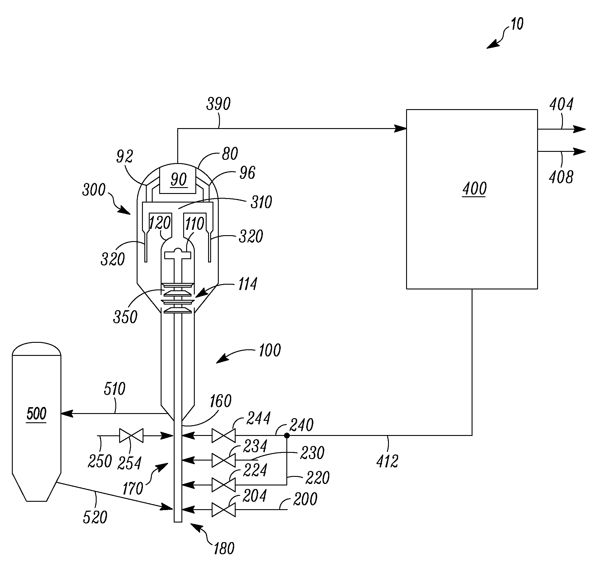
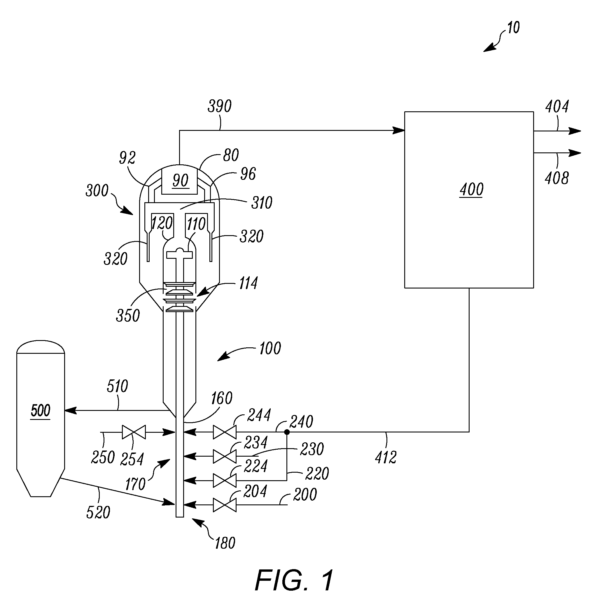
[0021]Referring to FIG. 1, a fluid catalytic cracking (hereinafter may be abbreviated “FCC”) system 10 can include a reaction zone 100, a disengagement zone 300, a separation zone 400, and a regeneration zone 500. Generally, the reaction zone 100 can include a reaction vessel 120 and at least one riser 160, which can have multiple injection points for receiving hydrocarbon streams. Moreover, process flow lines in the figures can be referred to as lines, pipes, conduits, feeds or streams. Particularly, a line, a pipe, or a conduit can contain one or more feeds or streams, and one or more feeds or streams can be contained by a line, a pipe, or a conduit.

[0022]In this exemplary fluid catalytic cracking system 10, one or more upper injection points 170, such as a second feed point 170, can be used in conjunction with one or more lower injection points 180, such as a first feed point 180, e.g., with a first feed 200. Namely, several streams 200, 220, 230, 240, and 250 can be, independent...


PUM

PropertyMeasurementUnit
residence timeaaaaaaaaaa
partial pressureaaaaaaaaaa
temperatureaaaaaaaaaa

Abstract

One exemplary embodiment can be a fluid catalytic cracking system. The system can include a reaction zone operating at conditions to facilitate olefin production and including at least one riser. The at least one riser can receive a first feed having a boiling point of about 180-about 800° C., and a second feed having more than about 70%, by weight, of one or more C4+ olefins.

Description

FIELD OF THE INVENTION[0001]This invention generally relates to fluid catalytic cracking systems, such as those receiving at least one of a hydrocarbon feed and a hydrocarbon stream.DESCRIPTION OF THE RELATED ART[0002]Catalytic cracking can create a variety of products from larger chain hydrocarbons. Often, a heavier hydrocarbon feed, such as a vacuum gas oil, is provided to a catalytic cracking reactor, such as a fluid catalytic cracking reactor. Various products can be obtained from such a system, including a gasoline product and / or other light products, such as ethylene and propylene.[0003]In such systems, it is generally desirable to obtain more of certain products, such as ethylene and propylene. Particularly, ethylene and propylene can be used in subsequent products to manufacture, e.g., plastics. However, the desire to maximize the yield of light olefins can be limited due to process constraints, such as undesirable side reactions. Thus, it would be advantageous to provide a ...

Claims


Application Information

Patent Timeline
Patent Type & Authority Applications(United States)
IPC IPC(8): B01J8/24
CPCC10G11/18C10G2300/1044C10G2400/20C10G2300/301C10G2400/02C10G2300/1088B01J8/24B01J20/18C07C4/06
Inventor MEHLBERG, ROBERT L.COUCH, KEITH ALLENHEDRICK, BRIAN W.FEI, ZHIHAO
Owner UOP LLC
Why Eureka
Try Eureka