Oil pan

a technology of oil pans and oil cylinders, applied in the direction of lubricant mounting/connection, combustion air/fuel air treatment, machines/engines, etc., can solve the problems of insufficient rigidity, noise, and considerable reduction of rigidity of reservoirs, so as to reduce energy consumption, reduce viscosity, and enhance heat insulation properties

Inactive Publication Date: 2010-07-01
DAIKYONISHIKAWA CORP
View PDF13 Cites 31 Cited by
  • Summary
  • Abstract
  • Description
  • Claims
  • Application Information

AI Technical Summary

Benefits of technology

[0048]In this case, the bottom of the main chamber has a multiple structure made of the outer wall and the inner wall, thereby enhancing heat insulating properties. Accordingly, in particular, oil in the main chamber i...

Problems solved by technology

Accordingly, the oil pan can have a lighter weight than a steel-made oil pan, but might have insufficient rigidity.
In particular, the presence of the opening in the oil reservoir considerably reduces rigidity.
Insufficient rigidity of the oil pan might cause each part of the oil pan to easily vibrate with vibration of the power unit, thereby producing noise.
In addition, deformation and damage are likely to occur upon application of external forces.
In addition, even if the rib is provided outside the op...

Method used


Image

  • Oil pan
  • Oil pan
  • Oil pan

Examples


embodiment 1

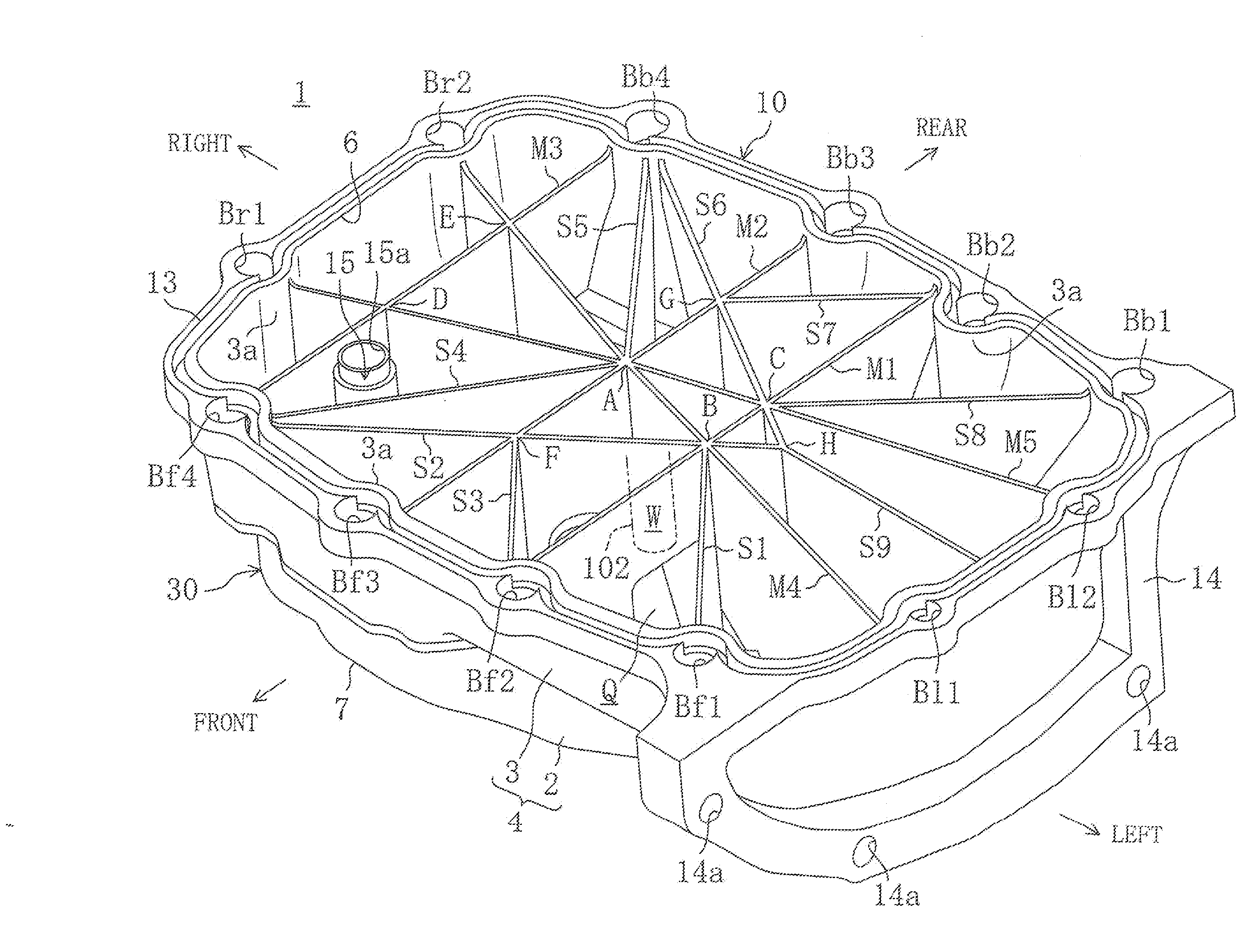
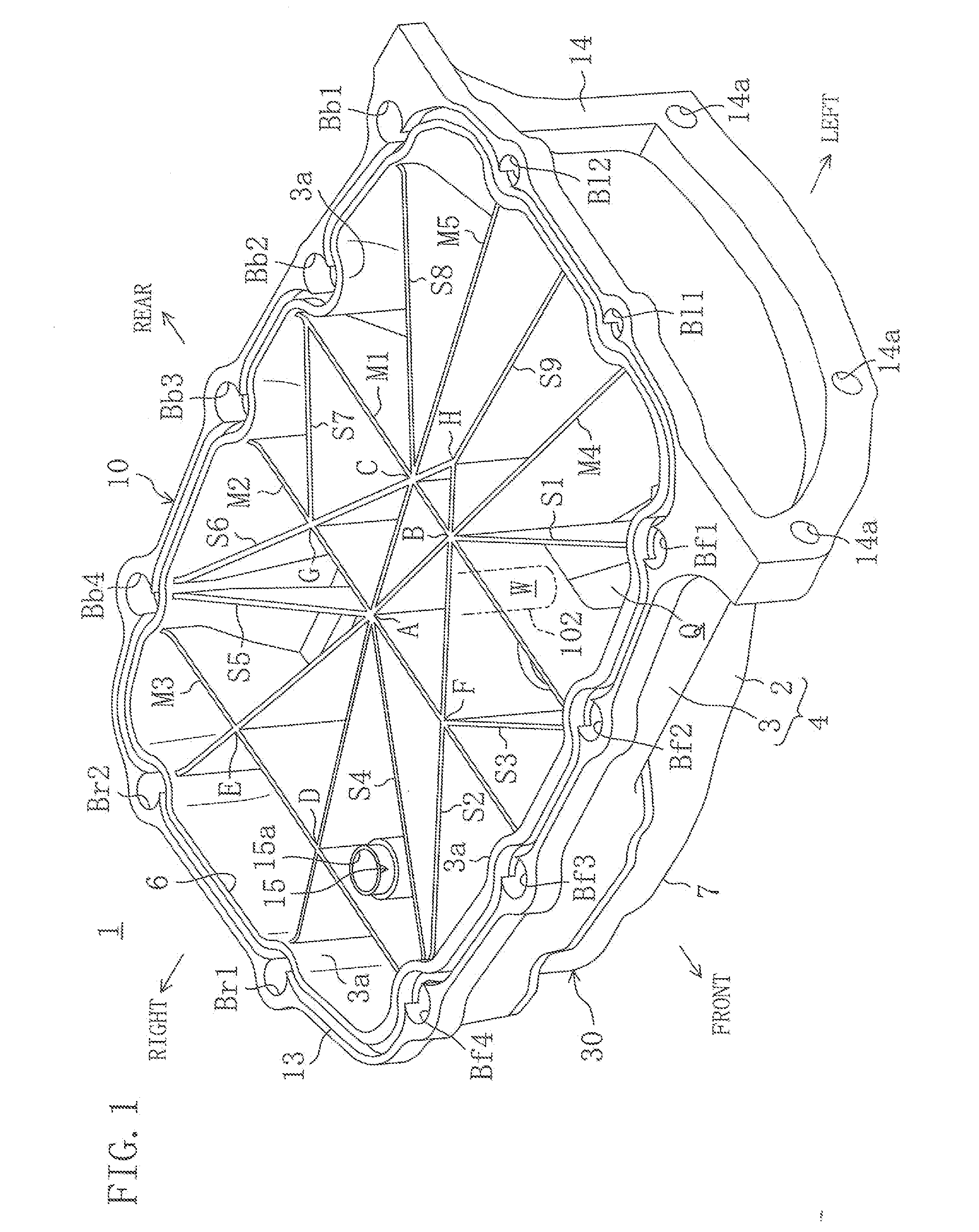
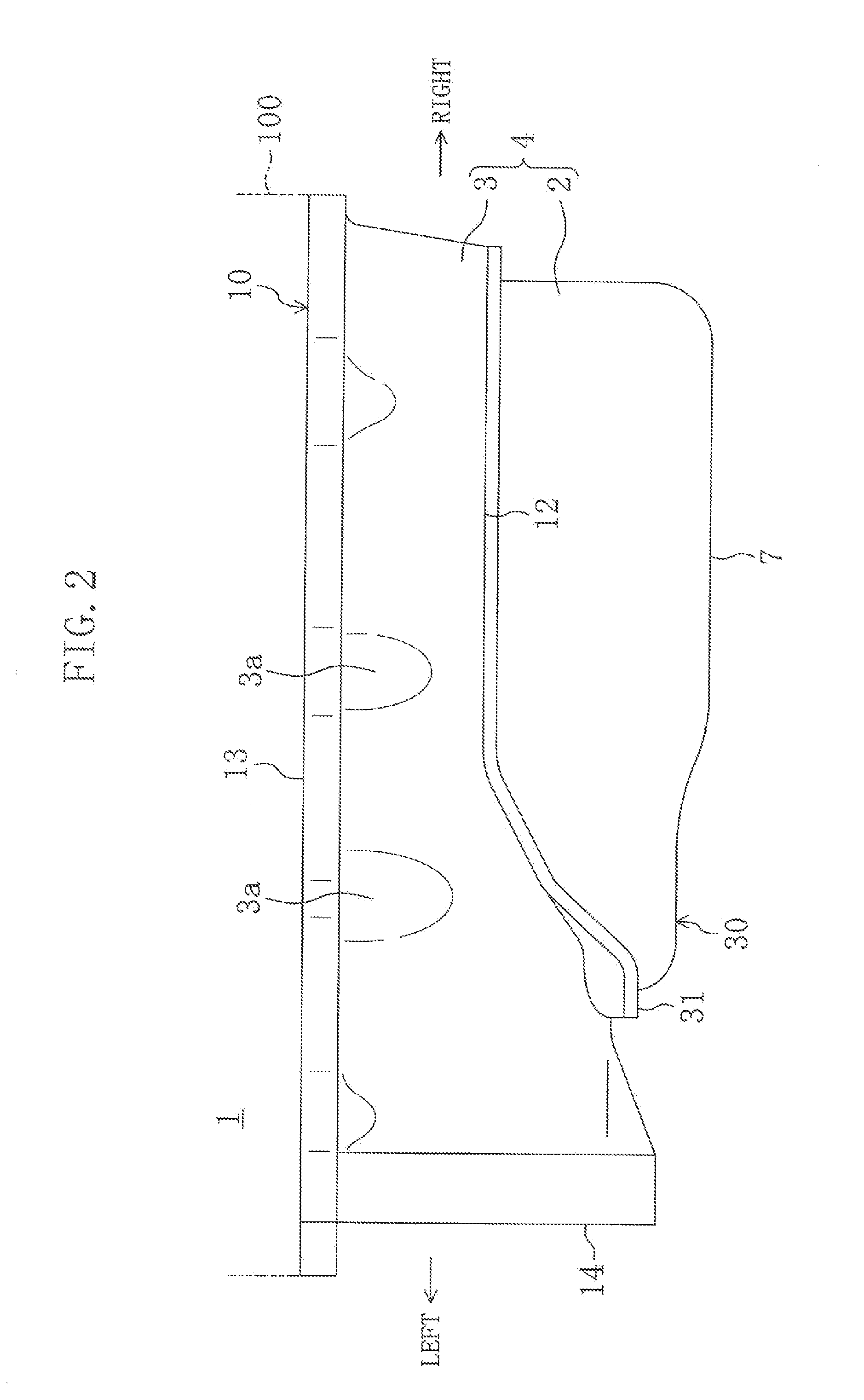
[0074]FIG. 1 illustrates an oil pan 1 according to a first embodiment of the present invention. The oil pan 1 is intended to be used in an engine (not shown) mounted on an engine compartment at the front of an automobile, and is attached to the lower surface of a cylinder block 100 of the engine, as illustrated in FIGS. 2 and 3. The engine mounted in the engine compartment is positioned such that the crank shaft extends in the lateral direction of the automobile.

[0075]In the embodiments, the front side of the automobile is referred as the “front,” the rear side of the automobile is referred to as the “rear,” the left side of the automobile is referred as the “left,” and the right side of the automobile is referred as the “right,” for simplicity.

[0076]The oil pan 1 includes: a recessed oil reservoir 4 formed by a bottom wall 2 covering substantially the entire bottom surface of the cylinder block 100 and a peripheral wall 3 rising from the periphery of the bottom wall 2; first throug...

embodiment 2

[0157]FIGS. 22-24 illustrate a second embodiment of the present invention. An oil pan 1 according to the second embodiment is different from that of the first embodiment only in that the oil strainer 5 is separated from the oil reservoir 4, and in the structures of the ribs M1 through M4. Thus, in the following description, the same reference numerals denote the same components in the first embodiment, and only different aspects will be described in detail.

[0158]Specifically, as illustrated in FIGS. 22 and 23, the oil pan 1 of the second embodiment includes first through fourth main ribs M1 through M4. The first and second main ribs M1 and M2 are spaced apart from each other, and extend substantially in parallel with each other in the front-to-rear direction. The third and fourth main ribs M3 and M4 are spaced apart from each other, and extend substantially in parallel with each other in the right-to-left direction. Intermediate portions of the first and second main ribs M1 and M2 i...


PUM


Abstract

An oil pan made of resin includes an oil reservoir. The oil reservoir includes a bottom wall and a peripheral wall rising from a periphery of the bottom wall and having an opening at a top of the oil reservoir. A rib is provided in the oil reservoir.

Description

BACKGROUND[0001]1. Technical Field[0002]The present disclosure relates to oil pans made of resin.[0003]2. Background Art[0004]Conventional power units such as engines and automatic transmissions are provided with oil pans for temporarily reserving oil circulated in the power units (see, for example, Japanese Patent Publications Nos. 2-264109 and 2006-283617). An oil pan described in Japanese Patent Publication No. 2-264109 includes an oil reservoir having a bottom wall and a peripheral wall rising from the periphery of the bottom wall. An opening through which oil circulated in a power unit flows into the oil reservoir is formed at the top of the oil reservoir. A plurality of ribs and a fastening portion fastened to the power unit are provided in the oil reservoir, and are located closer to the outside than the opening of the oil reservoir.[0005]An oil pan described in Japanese Patent Publication No. 2006-283617 is formed out of a resin material, and includes an oil reservoir having...

Claims


Application Information

Patent Timeline
IPC IPC(8): F01M11/03F02F7/00
CPCF01M11/0004F01M2011/002F01M2011/007F01M2011/0087F01M2011/0091
Inventor ENOKIDA, SATOSHI
Owner DAIKYONISHIKAWA CORP
Why Eureka
Try Eureka