Pressure-Resistant Container

a container and pressure-resistant technology, applied in the direction of container discharging methods, vessel construction details, transportation and packaging, etc., can solve the problems of gap generation, creeping in the resin of the inner shell, and insufficient gas sealing properties of the conventional gas tank, etc., to achieve high pressure resistance properties of the container

Active Publication Date: 2010-07-01
SUBARU CORP
View PDF27 Cites 21 Cited by
  • Summary
  • Abstract
  • Description
  • Claims
  • Application Information

AI Technical Summary

Benefits of technology

[0043]According to the invention described in claim 1, the first seal peripherally contacts with the inner peripheral surface of the mouth ring which is exposed between the inner shell and the pressing member and a periphery of the opening of the inner shell in an integral manner. Consequently, the gas sealing property of the edge part of the covering where the inner shell and the mouth ring adhere to one another can be enhanced, and thereby an effect of realizing the high pressure resistance property of the container is obtained.
[0044]According to the invention described in claim 2, the first seal peripherally contacts with the inner peripheral surface of the mouth ring which is exposed between the inner shell and the pressing member, the periphery of the opening of the inner shell and the pressing member in an integral manner. Consequently, the edge part of the covering where the inner shell and the mouth ring adhere to one another can be sealed. Furthermore, because the second seal seals the part between the outer peripheral surface of the inner end part of the valve and the inner peripheral surface of the pressing member, the internal gas will not go around the end part of the pressing member at the outer side of the container to enter the edge part of the covering where the inner shell and the mouth ring adhere to one another, and consequently the gas sealing property of the edge part of the covering where the inner shell and the mouth ring adhere to one another can be enhanced. Thus, the effect of realizing the high pressure resistance property of the container is obtained.
[0045]Moreover, because it is sufficient for the inner shell to cover at least the end surface of the mouth ring at the inner side of the container, a molding technique having good productivity, such as the blow molding, can be applied to the inner shell before attaching the mouth ring thereto, and the mouth ring that has been configured separately can be attached to the inner shell by adhesion, welding or the like, after the molding of the inner shell. Consequently, the effect of making the manufacturing of the pressure-resistant container easy to reduce the cost is obtained.

Problems solved by technology

The conventional gas tank yet has insufficient gas sealing property of the joined part or the interface part of the inner shell and the mouth ring portion.
Consequently, even when gas leakage does not occur just after the manufacturing of the pressure-resistant container, creeping occurs in the resin of the inner shell to shrink and a gap is generated at an interface of the inner shell and the mouth ring while using the container for a long time.
Thus, there is a possibility that gas leakage might occur from the gap at the interface.
Consequently, there is possibility that gas leakage might occur by the same reason as described above.
Therefore, even when a gas leakage does not occur right after the manufacturing of the pressure-resistant container, the plastic of the inner shell creeps and the inner shell shrinks while the container is being used for a long time.
Thus, there is a possibility that gas leakage might occur in the pressure-resistant container similarly as the pressure-resistant containers described in Patent Documents 2 and 3.
Even when it is tempted to increase the number of sealing ring in response to the shrinking of the inner shell, the product container is needed to be disassembled, and further in the case of exchanging a deteriorated sealing, the product container is also needed to be disassembled, and it is not only troublesome but also uneconomical.
However, in this method, although one side is the pressing member made of metal which can secure the surface accuracy relatively easily, the other side is made of plastic which cannot secure the surface accuracy.
Consequently, this structure lacks the reliability of sealing.
However, the bending strength of the mouth ring at the projecting part by the internal pressure of the tank becomes severe in an ultra high pressure tank, such as 70 MPa, and there is a possibility that the breaking of the mouth ring occurs in a repetition cycle.

Method used


Image

  • Pressure-Resistant Container
  • Pressure-Resistant Container
  • Pressure-Resistant Container

Examples


first embodiment

[0053]First, the first embodiment of the present invention will be described with reference to FIGS. 1 to 3.

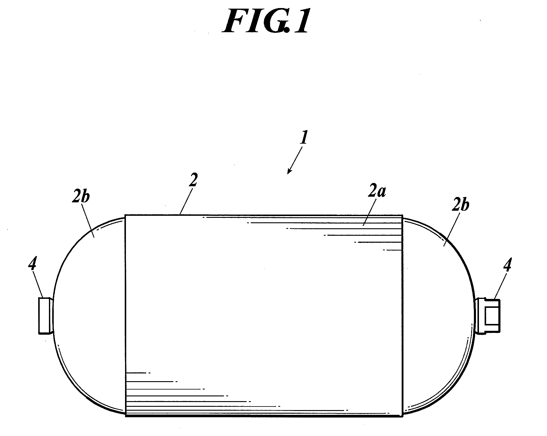
[0054]FIG. 1 is an outline view of the entire pressure-resistant container according to the first embodiment of the present invention.

[0055]As shown in FIG. 1, the pressure-resistant container 1 of the present embodiment comprises an outer shell 2 and mouth rings 4. The outer shell 2 is made of a composite material of a fiber reinforced resin such as CFRP, and is composed of a cylinder part 2a and dome parts 2b and 2b continuing from both ends of the cylinder part 2a. The outer shell 2 covers an inner shell (omitted from the drawing). The mouth rings 4 are provided at the peak parts of the dome parts 2b and 2b. Only one mouth ring may be provided.

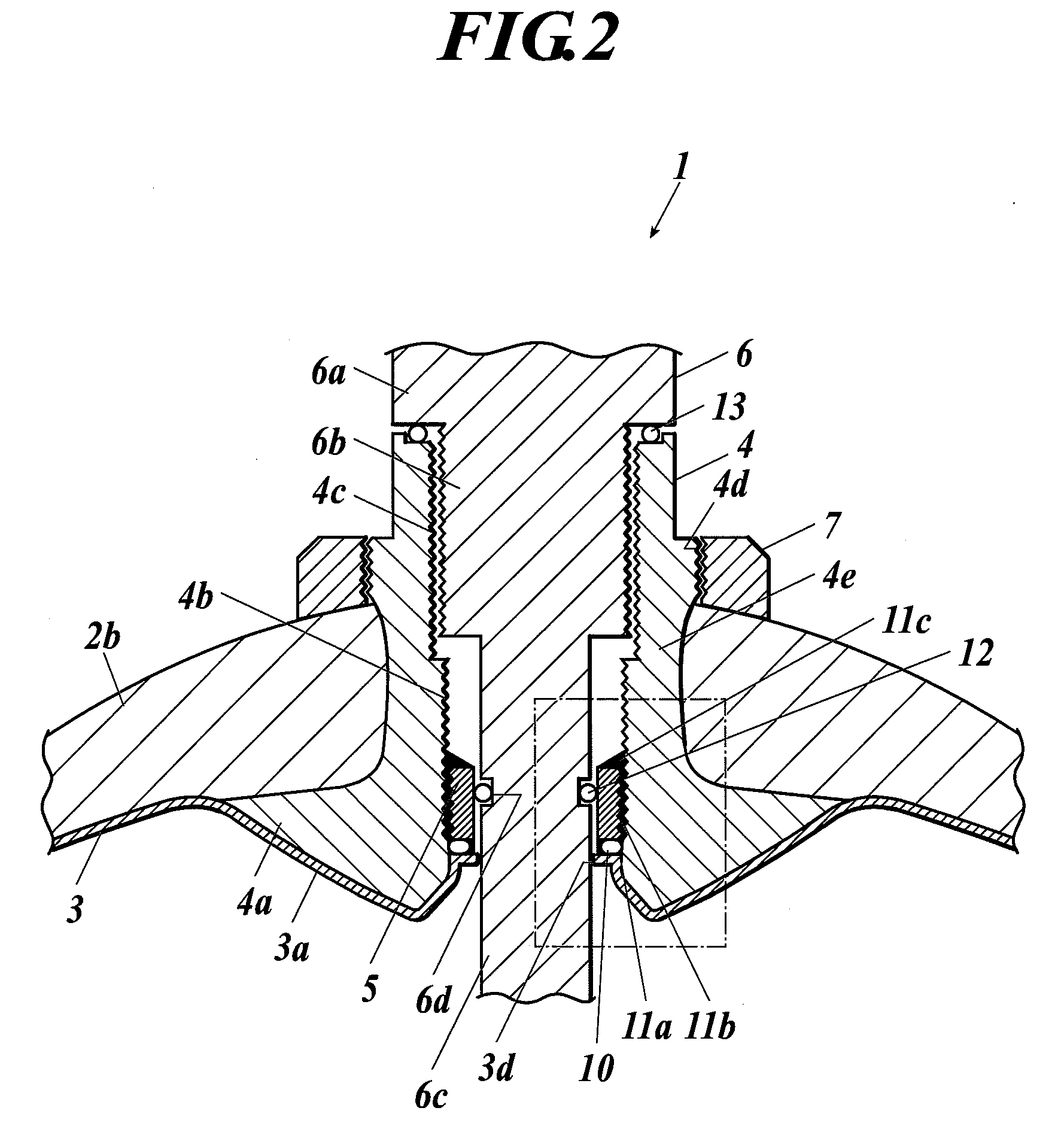
[0056]FIG. 2 is a sectional view of a mouth ring portion of the pressure-resistant container 1. FIG. 3 is a partially enlarged view of FIG. 2. As shown in FIG. 2 or 3, an opening 3d connected to the mouth rings 4 is formed at the inne...

second embodiment

[0110]Next, a second embodiment of the present invention will be described with reference to FIG. 4. FIG. 4 is a sectional view of a mouth ring portion of the pressure-resistant container according to the second embodiment of the present invention. The pressure-resistant container 20 of the embodiment is different from the pressure-resistant container 1 of the first embodiment in that the O-ring 10 constituting the first seal is excluded and that the first seal is composed only with the liquid sealant 11a. The liquid sealants 11b and 11c are not shown. However, they may be provided.

[0111]As described above, in the case of the pressure-resistant container 1 of the first embodiment, the reliability of the sealing is improved by using the liquid sealant 11a in addition to the O-ring 10 as the first seal.

[0112]When the O-ring 10 is applied, there is an advantage that an uniform sealing part can be obtained comparing to when only the liquid sealant 11a is used. However, in the case where...

third embodiment

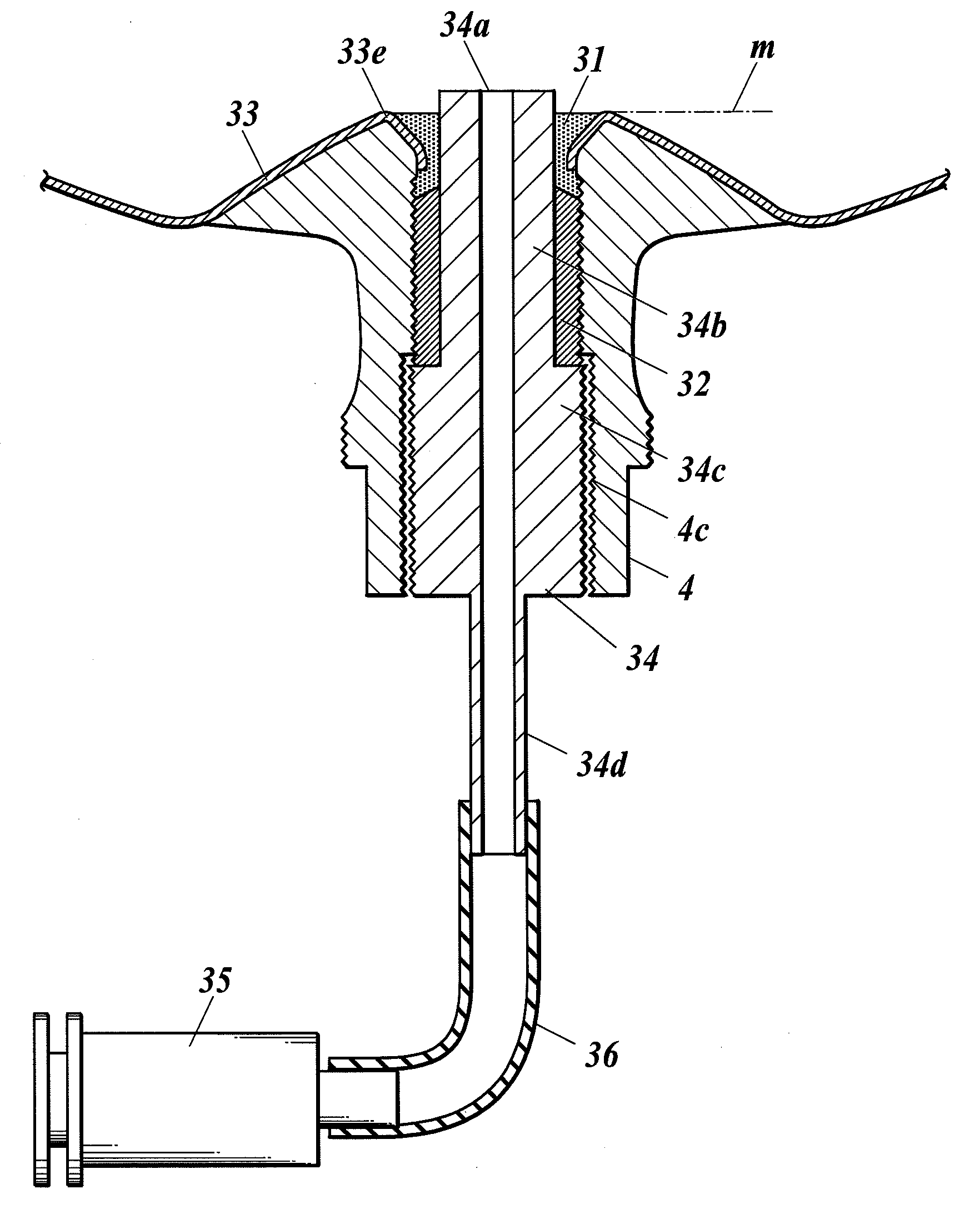
[0113]Next, a third embodiment of the present invention will be described with reference to FIG. 5. FIG. 5 is a sectional view of a mouth ring portion of the pressure-resistant container according to the third embodiment of the present invention. The pressure-resistant container 30 of the embodiment is different from the pressure-resistant container 20 of the second embodiment in that the first seal is a liquid sealant 31 and that the liquid sealant 31 peripherally contacts with and covers the inner peripheral surface of the mouth ring 4 which is exposed between the inner shell 33 and the pressing member 5 and periphery of the opening of the inner shell 3 and does not contact with the pressing member 5. It is preferable that the liquid sealants 11b and 11c are provided to the pressing member 5 similarly as in the first embodiment, although they are not shown.

[0114]As shown in FIG. 5, the inner shell 33 covers along the mouth ring 4 to the circumference of the opening of the inner sh...


PUM

PropertyMeasurementUnit
pressuresaaaaaaaaaa
pressuresaaaaaaaaaa
pressureaaaaaaaaaa

Abstract

In a pressure-resistant container 1, a peripheral part 3a of an opening 3d of an inner shell 3 is attached to an end surface of a mouth ring 4 at an inside of the container so as to cover thereof. Further, the pressure-resistant container 1 comprises a cylindrical pressing member 5 which is screwed into an inner peripheral surface 4b of the mount ring 4, an inner peripheral surface b (FIG. 3) of the mouth ring 4 which exposes between the inner shell 3 and the pressing member 5, a first seal (an O-ring 10 and an liquid sealant 11a) which peripherally contacts with the inner shell and the pressing member, a valve 6 having a screw part 6b which screws into an inner periphery 4c of the mouth ring at outside of the container than the pressing member and an inner end part 6c which is inserted in the hole part of the pressing member and a second seal (an O-ring 12) to seal between an outer peripheral surface of the inner end part 6c and an inner peripheral surface of the pressing member. Further, the pressure-resistant container 1 comprises a third seal (an O-ring 13).

Description

TECHNICAL FIELD[0001]The present invention relates to a pressure-resistant container in which an inner shell made of a resin is covered with an outer shell made of a fiber reinforced composite material.BACKGROUND ART[0002]In recent years, the so-called nonpolluting automobiles have been developed, and a part of them has been put to practical use with the aim of preventing the environmental deterioration caused by the exhaust gas of automobiles. For example, an automobile operating by means of a natural gas in which methane is the main component as the fuel has been authorized as a low pollution automobile, and about one million units of the automobiles have been actually used already all over the world.[0003]Moreover, it is thought that a fuel cell powered automobile using hydrogen as its fuel will substitute for most of the current gasoline-driven automobiles in the future. There is a possibility that the natural gas and hydrogen that are used here are compressed natural gas and co...

Claims


Application Information

Patent Timeline
Patent Type & Authority Applications(United States)
IPC IPC(8): F17C1/00
CPCF16J13/12F17C13/06F17C2205/0305F17C2205/0311Y02E60/321F17C2201/0109F17C2203/0619F17C2203/066F17C2203/0663F17C2209/2127F17C2209/2154F17C2209/221F17C2209/227F17C2209/228F17C2209/234F17C2221/012F17C2221/033F17C2223/0161F17C2223/033F17C2260/011F17C2260/036F17C2270/0168Y02E60/32
Inventor MATSUOKA, SEIICHIARAKAWA, YOJI
Owner SUBARU CORP
Why Eureka
Try Eureka