
Optical Member With Retardation Control Function And Liquid Crystal Display

a technology of optical member and retardation layer, applied in the direction of optics, optical elements, instruments, etc., can solve the problems of difficult to secure a definite cell gap and visual observability level, and achieve the effect of reducing the number of liquid crystal cells, and effective inhibiting the retardation layer

Inactive Publication Date: 2010-07-01
DAI NIPPON PRINTING CO LTD
View PDF3 Cites 6 Cited by
  • Summary
  • Abstract
  • Description
  • Claims
  • Application Information

AI Technical Summary

Benefits of technology

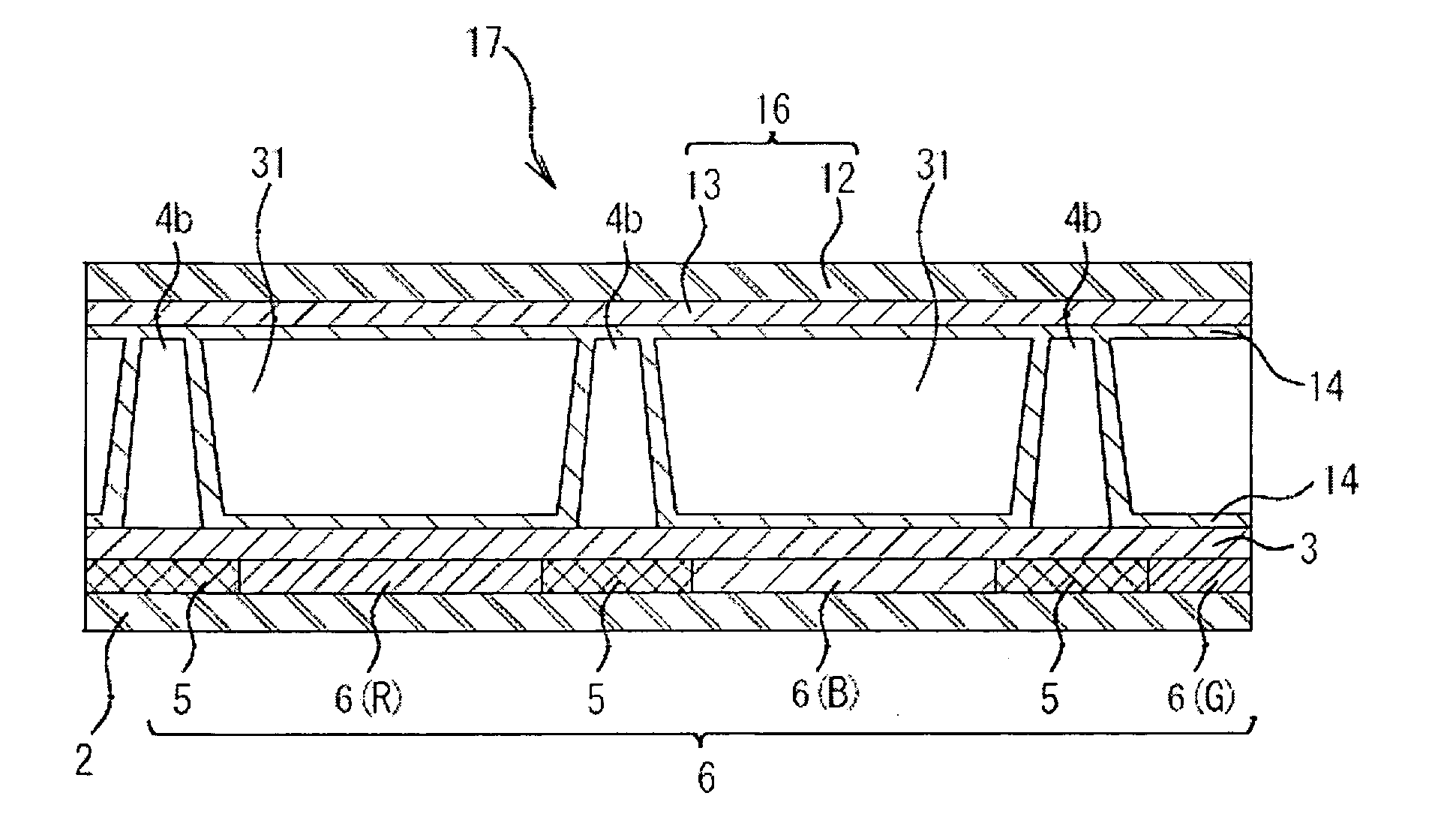
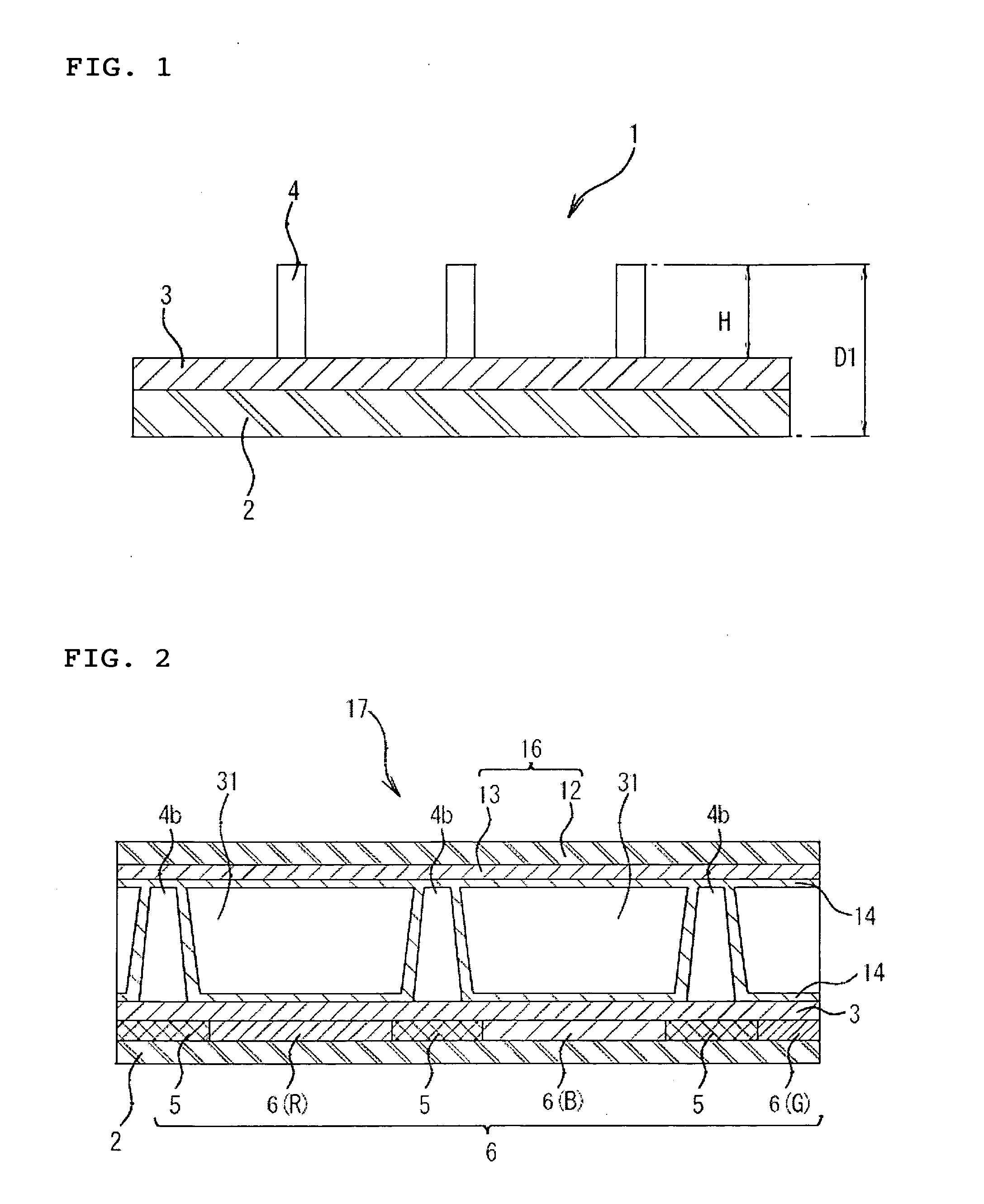
[0036]According to the invention, a sum total of lower bottom areas of columnar structures disposed in an effective display region on a retardation layer is 0.3% or more of the surface area of the effective display region. With this configuration, even when external pressure is applied in a thickness direction of a liquid crystal cell that is formed by use of the invention, the columnar structure is effectively inhibited from subsiding in the retardation layer. As a result, a thickness of a cell gap is inhibited from locally varying, whereby the visually observable brightness unevenness due to a variation of a thickness of a liquid crystal cell, which has been problematic, is preferably inhibited from occurring. Accordingly, when the invention is applied, high quality image display is obtained even when a liquid crystal panel obtained by only laminating a polarization plate and so on to a liquid crystal cell is used as a display of a mode where a liquid crystal panel is exposed to an observer side.
[0037]In particular, according to the invention of claim 2 where the columnar structure is formed tapered, a sum total of areas of upper bottom surfaces of the columnar structures may be designed smaller than a sum total of areas of lower bottom surfaces of the columnar structures in contact with a retardation layer that is a base material surface. Thereby, in comparison with a columnar structure having substantially the same sectional area in a height direction of the columnar structure or the like, a sum total of volumes of the columnar structures may be suppressed low with respect to an increase in a sum total of the areas of the lower bottom surfaces of the columnar structures. Accordingly, when a liquid crystal cell is formed with a retardation-controlling optical member of the invention, a sum total amount of volumes that the columnar structures occupy in a space secured by the columnar structures is suppressed smaller. As a result, a driving liquid crystal material that is filled in the space is filled smoothly, so that the productivity of liquid crystal cells is improved.
[0038]Furthermore, the invention where a columnar structure is formed tapered has advantages as described below in a liquid crystal cell where, after columnar structures are formed on an upper surface of the retardation layer, an alignment film for promoting the orientation of a driving liquid crystal material is scheduled to be formed on an upper surface of the retardation layer including the columnar structures. That is, in a tapered columnar structure, an alignment control surface continuing from the retardation layer surface to the columnar structure side surface is gradual in comparison with a columnar structure having substantially the same cross-section in a height direction such as a cylinder. As a consequence, a driving liquid crystal material may be desirably aligned in a desired direction even in the proximity of the columnar structure, so that the driving liquid crystal material in the proximity of the columnar structure is inhibited from causing disturbance of the alignment. Accordingly, a discrimination line that causes the light leakage and is caused by the alignment defect is inhibited from occurring.
[0039]Furthermore, when the columnar structure of the invention is formed tapered, with a sum total of areas of lower bottom surfaces of columnar structures increasing, a sum total of areas of upper bottom surfaces is designed smaller than the sum total of the areas of the lower bottom surfaces. That is, a buffering region may be disposed not in the proximity of the lower bottom surface of the columnar structure, but in the proximity of the upper bottom surface having a smaller sectional area, so that the hardness in the proximity of the upper bottom surface can be designed intentionally smaller. As a result, when the invention provided with tapered columnar structures and a counter substrate are combined to form a liquid crystal cell, an adhesion margin when both substrates are assembled in a cell may be obtained in the proximity of the upper bottom surface of the columnar structure that is designed smaller in the hardness. Accordingly, the adhesion margin is preferably secured.

Problems solved by technology

However, since the retardation layer is generally low in the hardness, there is a problem in that, when the retardation layer comes into point contact with the beads, the beads subside in the retardation layer, thereby making it difficult to secure a definite cell gap.
In general, when the cell gap varies (decreases) by substantially 15% partially in a display area, the transmittance is deteriorated by substantially 4% to result in a visually observable level as the brightness unevenness.

Method used


Image

  • Optical Member With Retardation Control Function And Liquid Crystal Display
  • Optical Member With Retardation Control Function And Liquid Crystal Display
  • Optical Member With Retardation Control Function And Liquid Crystal Display

Examples


example 1

Formation of Colored Layer

[0125]With alkali-free glass (trade name: NA35, produced by NH Technoglass Co., Ltd.) as a substrate, first, a light shielding region was formed, and then, transparent colored regions of red, green and blue color were formed between the light shielding regions by use of colored resists shown below according to a general photolithography process, thereby to constitute a colored layer having a thickness of substantially 2.0 μm.

[0126](Preparation of Colored Resist)

[0127]In order to form a light shielding region and transparent colored regions of three colors of red (R), green (G) and blue (B), pigment dispersion photoresists shown below were used as coloring materials. The pigment dispersion photoresist was obtained in such a manner that, with a pigment as a coloring material, beads were added to a dispersion composition (containing a pigment, a dispersing agent and a solvent), and the mixture was dispersed for 3 hr by a dispersing unit, followed by mixing a d...

example 2

[0182]In Example 2, a retardation-controlling optical member was formed in the same manner as in Example 1, except that a shape of a columnar structure was formed into a cylinder having a lower bottom surface of 12μφ; only 80,000 positions were selected per 100 cm2 on a retardation layer as positions scheduled to form columnar structures, without executing additive selection of one position to each of 80,000 positions; the number of the columnar structures disposed was set to 80,000 positions; and an occupation area rate of the lower bottom surface of the columnar structures to the surface area of the retardation layer was set to 0.36%.

reference examples 1 to 3

[0206]In Reference Example 1, a retardation-controlling optical member was formed in the same manner as in Example 1, except that a columnar structure was formed with taper such that a ratio of a cross sectional area of the columnar structure cut at a height of 90% from a lower bottom surface of the columnar structure to a lower bottom surface of the columnar structure (hereinafter, simply referred to as well as “90% height cross section ratio”) was set to 20%.

[0207]Similarly to Reference Example 1, a retardation-controlling optical member was formed as Reference Example 2 in the same manner as in Example 1 except that the 90% height cross section ratio was set to 3%, and a retardation-controlling optical member was formed as Reference Example 3 in the same manner as in Example 1 except that the 90% height cross section ratio was set to 70%.

[0208](Evaluation 3)

[0209]Loading and Unloading Test 2

[0210]In order to simulatively evaluate the securement of the margin when a retardation-co...


PUM

PropertyMeasurementUnit
transmittanceaaaaaaaaaa
thicknessaaaaaaaaaa

Abstract

The invention provides a retardation-controlling optical member that includes a retardation layer obtained by aligning and fixing crosslinkable liquid crystal molecules and columnar structures disposed on the retardation layer. When a liquid crystal cell is formed by use of the retardation-controlling optical member, the columnar structures are effectively inhibited from subsiding in the retardation layer to locally make the cell gap smaller even when pressure is externally applied in a thickness direction of the liquid crystal cell.A sum total of lower bottom areas of columnar structures disposed on a retardation layer is made larger sufficiently compared to a total area of, in particular, an effective display region of a retardation layer surface where the columnar structures are disposed, whereby pressure applied from a thickness direction is dispersed.

Description

TECHNICAL FIELD[0001]The present invention relates to an optical member with a retardation control function and a liquid crystal display using the optical member, and in particular, to a liquid crystal display or an electroluminescence display excellent in the display quality and an optical member used therefor.BACKGROUND ART[0002]In recent years, from high display characteristics, liquid crystal displays of In-Plane Switching mode and Multi-Domain Vertical Alignment mode are widely used. In order to expand a viewing field angle in the liquid crystal displays, a method where a film having the optical anisotropy is adhered to the outside of a liquid crystal cell has been widely used.[0003]Recently, instead of the retardation film, a retardation layer that is formed in a cell with a liquid crystal material has been proposed. The retardation layer is called a so-called in-cell type. As a method of forming a retardation layer inside of a liquid crystal cell by use of a liquid crystal ma...

Claims


Application Information

Patent Timeline
Patent Type & Authority Applications(United States)
IPC IPC(8): G02F1/1347G02F1/13
CPCG02B5/3016G02F1/13363G02F1/13394G02F2001/133565G02F2001/133633G02F2001/133715G02F2413/01G02F1/133565G02F1/133633G02F1/133715
Inventor MORIYA, NORIHISAHAYASHI, SHINJINAKATSUGAWA, YUJI
Owner DAI NIPPON PRINTING CO LTD
Learn More