Laser projector
a projector and laser technology, applied in the field of projectors, can solve the problems of short life, low light use efficiency, limited reproducing range, etc., and achieve the effect of removing speckle nois
- Summary
- Abstract
- Description
- Claims
- Application Information
AI Technical Summary
Benefits of technology
Problems solved by technology
Method used
Image

Examples
first embodiment
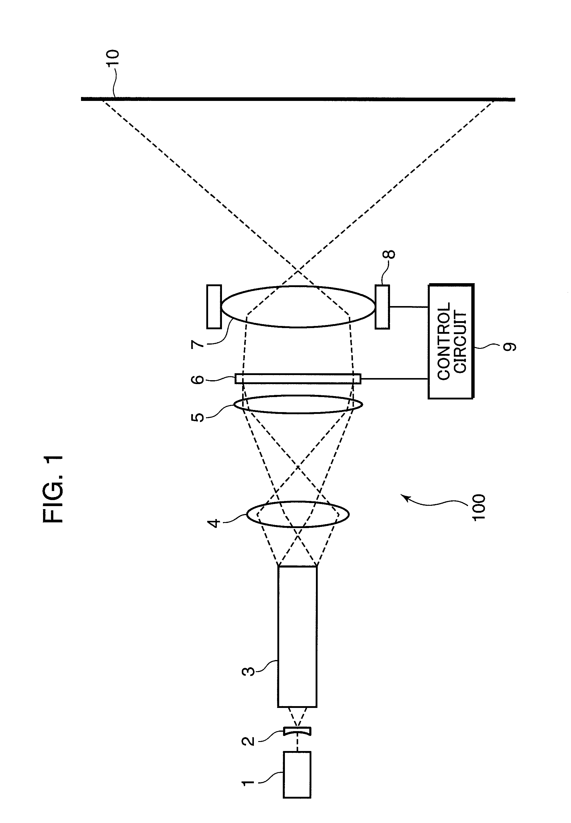
[0027]FIG. 1 is a schematic construction diagram of a laser projector 100 in the first embodiment of the invention. The laser projector 100 shown in FIG. 1 includes a laser light source 1, a lens 2, a rod integrator 3, a relay lens 4, a field lens 5, a two-dimensional light modulator 6, a projection optical system 7, a driver 8, and a control circuit 9.
[0028]Laser light emitted from the laser light source 1 is transmitted through the lens 2, subjected to beam shaping by the rod integrator 3, transmitted through the relay lens 4 and the field lens 5, and illuminates the two-dimensional light modulator 6. The two-dimensional light modulator 6 modulates the laser light in accordance with a video signal (a display signal) from the control circuit 9 to form an image. The projection optical system 7 enlarges and projects the image formed by the two-dimensional light modulator 6 on a display plane 10. In response to receiving a video signal from an external device, the control circuit 9 co...
second embodiment
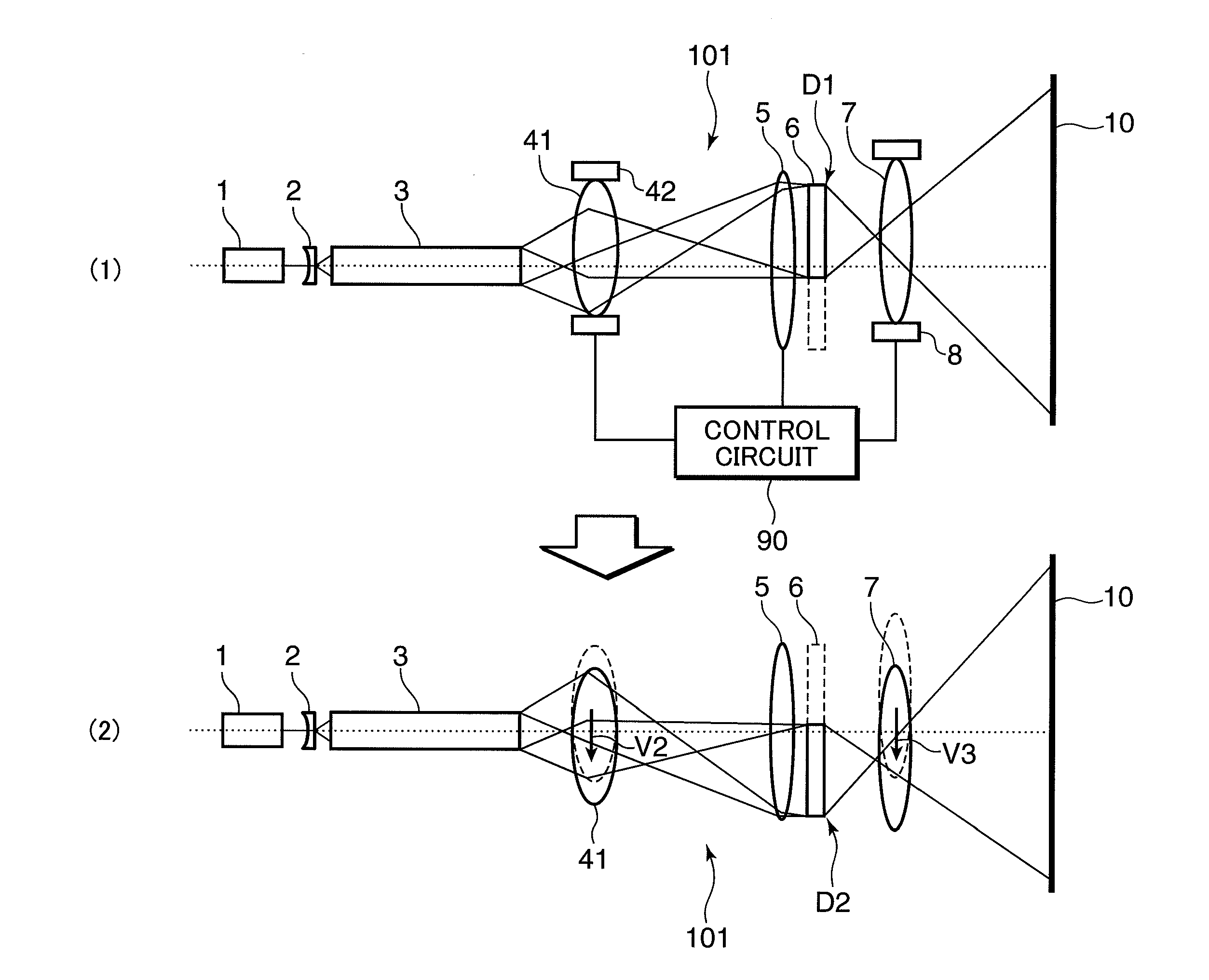
[0048]FIG. 3 is a schematic construction diagram of a laser projector 101 in the second embodiment, and shows a state that an illumination region of laser light is shifted in synchronism with shift of a display position D1, D2 of a two-dimensional light modulator 6 in the laser projector 101. In the section (2) of FIG. 3, to simplify the illustration, a driver 8 for a projection optical system 7, a driver 42 for a relay lens 41, and a control circuit 90 for controlling the drivers 8 and 42, and the two-dimensional light modulator 6 shown in the section (1) of FIG. 3 are not illustrated.
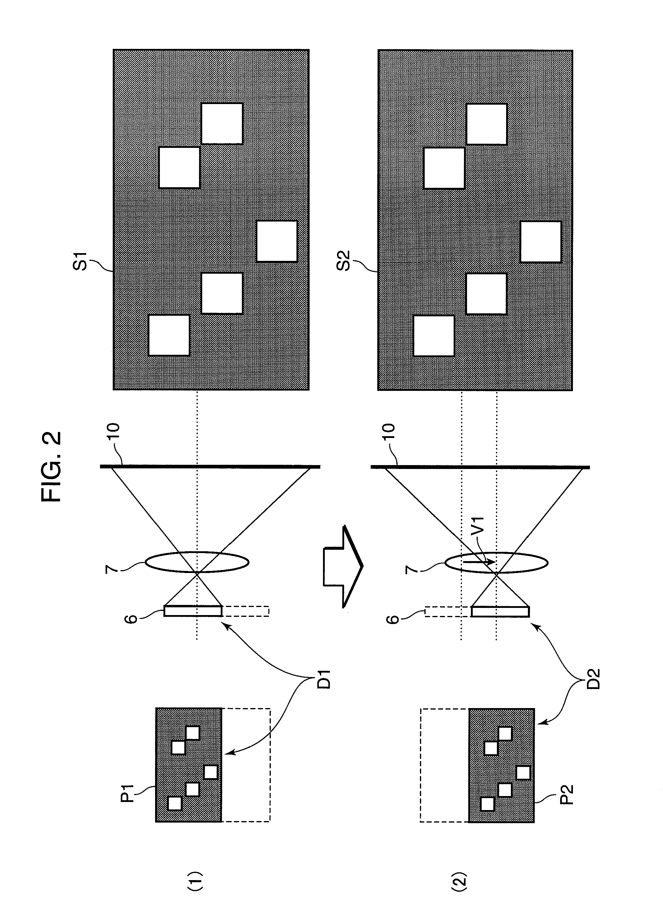
[0049]The second embodiment is different from the first embodiment in a point that the illumination region with respect to the two-dimensional light modulator 6 is also shifted in performing the display operation as shown in the sections (1) and (2) of FIG. 2. The shift operation of the illumination region is illustrated in FIG. 3. Specifically, the relay lens 41 is supported to be movable in a direct...
third and fourth embodiments
[0061]A laser light source such as a semiconductor laser, a solid-state laser, or a wavelength conversion laser may be used as a laser light source in the invention. The laser projector 100 shown in FIG. 1 is an example of using a single laser light source. In the case where a color image is displayed by using three colors of R, G and B, laser light sources for emitting laser light of three colors of R, G, and B may be used. A color laser projector 200 in the third embodiment shown in FIG. 4, and a color laser projector 300 in the fourth embodiment shown in FIG. 5 are construction examples using laser light sources for emitting laser light of three colors of R, G, and B. The number of laser light sources is not specifically limited, and laser light sources for emitting laser light of four or more colors may be used.
[0062]FIG. 4 is a schematic construction diagram of the color laser projector 200 in the third embodiment of the invention. In FIG. 4, to simplify the illustration, a dri...
PUM
 Abstract
Description
Claims
Application Information
 - R&D
- Intellectual Property
- Life Sciences
- Materials
- Tech Scout
- Unparalleled Data Quality
- Higher Quality Content
- 60% Fewer Hallucinations
Browse by: Latest US Patents, China's latest patents, Technical Efficacy Thesaurus, Application Domain, Technology Topic, Popular Technical Reports.
© 2025 PatSnap. All rights reserved.Legal|Privacy policy|Modern Slavery Act Transparency Statement|Sitemap|About US| Contact US: help@patsnap.com