

Solid electrolytic capacitor
a technology of electrolytic capacitors and solids, applied in the direction of liquid electrolytic capacitors, fixed capacitors, fixed capacitor details, etc., can solve the problems of increasing the cost of capacitors and preventing the capacitor from having a small size, so as to reduce the number of components and processes, reduce the cost, and the effect of small siz
- Summary
- Abstract
- Description
- Claims
- Application Information
AI Technical Summary
Benefits of technology
Problems solved by technology
Method used
Image

Examples
exemplary embodiment 1
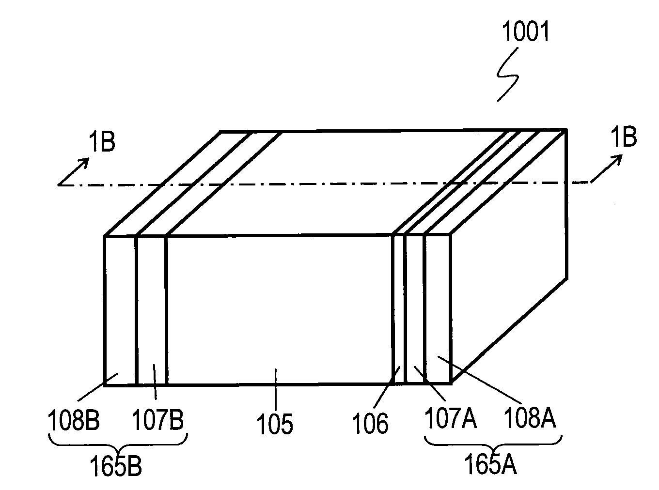
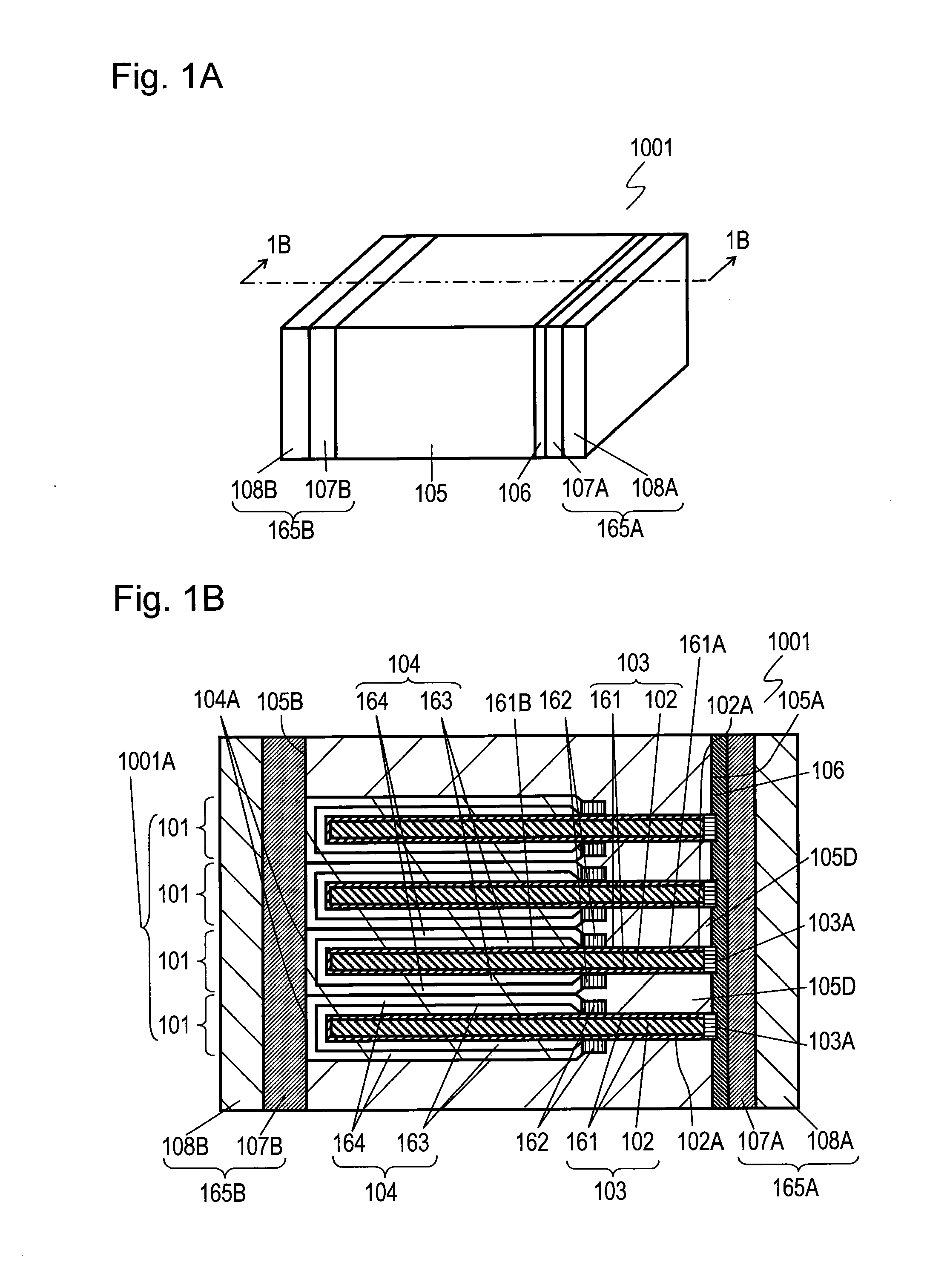
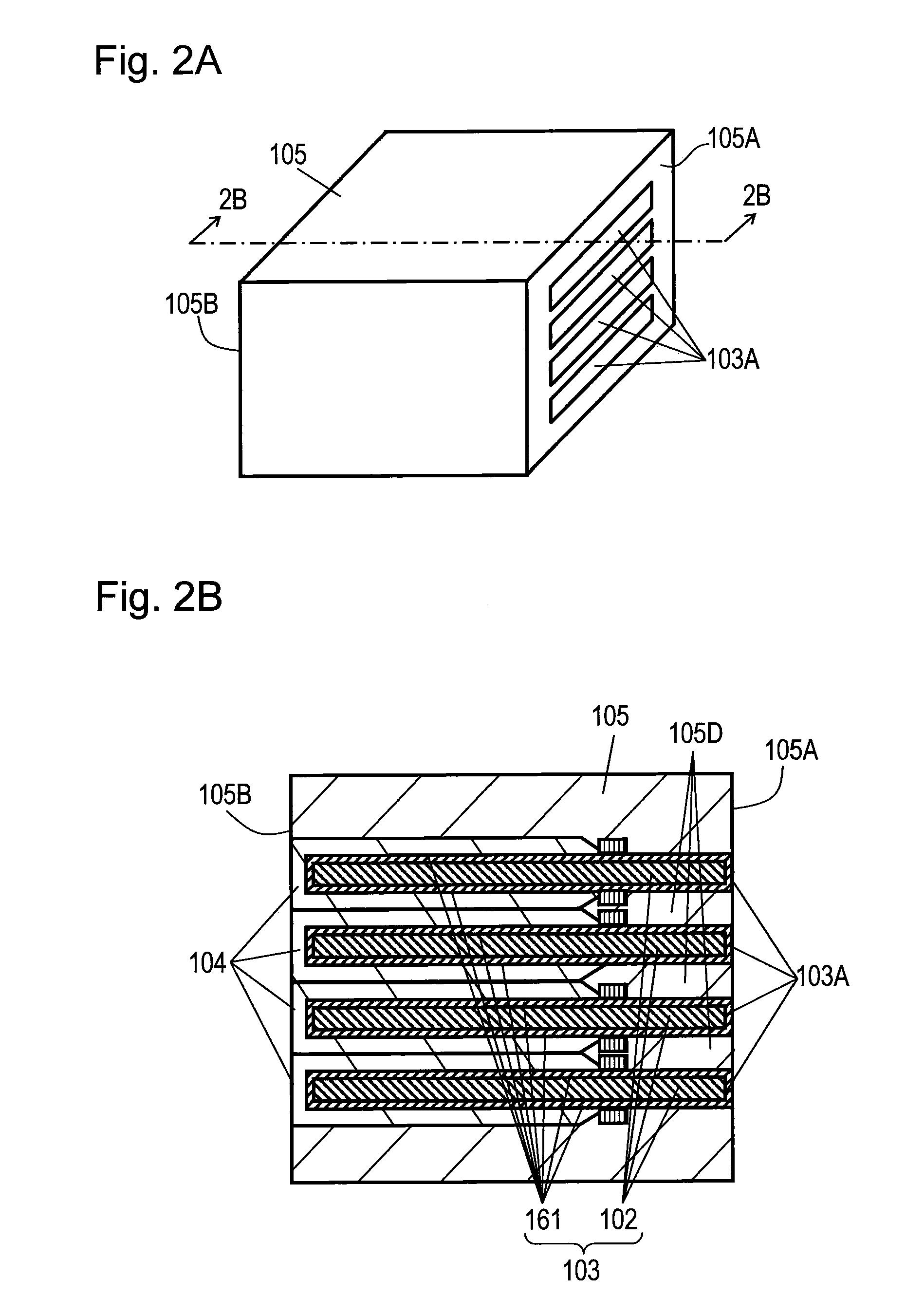
[0127]FIG. 1A is a perspective view of solid electrolytic capacitor 1001 in accordance with exemplary Embodiment 1 of the present invention. FIG. 1B is a sectional view of solid electrolytic capacitor 1001 on line 1B-1B shown in FIG. 1A. Solid Electrolytic capacitor 1001 according to Embodiment 1 is a chip solid electrolytic capacitor.
[0128]Solid electrolytic capacitor 1001 includes plural capacitor elements 101 which are stacked. Each capacitor element 101 includes positive electrode section 103 and negative electrode section 104. Surface 102A of positive electrode body 102 made of valve metal, such as aluminum foil, having a thickness of 0.1 mm is roughened. Dielectric oxide layer 161 is formed on surface 102A of positive electrode body 102. Resist 162 having an insulating property is formed on layer 161. Resist 162 separates dielectric oxide layer 161 into positive electrode deck 161A and negative electrode deck 161B. Solid electrolytic layer 163 made of conductive polymer is for...
exemplary embodiment 2
[0150]FIG. 5 is a sectional view of solid electrolytic capacitor 1002 in accordance with Exemplary Embodiment 2 of the invention for illustrating a method of manufacturing the capacitor. Solid electrolytic capacitor 1002 is a chip solid electrolytic capacitor. In FIG. 5, components identical to those of capacitor 1001 according to Embodiment 1 shown in FIGS. 1A to 3B are denoted by the same reference numerals, and their description will be omitted.
[0151]Solid electrolytic capacitor 1002 shown in FIG. 5 includes insulating resin layer 109 formed on a surface of positive electrode section 103 of capacitor element 101 in addition to solid electrolytic capacitor 1001 shown in FIG. 2B in accordance with Embodiment 1. Resin layer 109 has a thickness substantially equal to the height of negative electrode section 104 from dielectric oxide layer 161 so that the thickness of positive electrode section 103 can be substantially equal to that of negative electrode section 104. Resin layer 109 i...
exemplary embodiment 3
[0153]FIG. 6 is a sectional view of solid electrolytic capacitor 1003 in accordance with Exemplary Embodiment 3. In FIG. 6, components identical to those of capacitor 1001 according to Embodiment 1 shown in FIG. 1B are denoted by the same reference numerals, and their description will be omitted. Solid electrolytic capacitor 1003 is a chip solid electrolytic capacitor.
[0154]Solid electrolytic capacitor 1003 further includes substrate 110 having an insulating property and placed on a lower surface of stacked-element unit 1001A in addition to capacitor 1001. Substrate 110 is made of glass epoxy; however, it is not limited to this material. Capacitor 1003, a chip solid electrolytic capacitor, has so small size that the insulating resin of package 105 may not flow uniformly and steadily. Substrate 110 on the lower surface of stacked-element unit 1001A allows the resin to flow into unit 1001A uniformly even the size of capacitor 1003 is small. The resin thus can spread uniformly around e...
PUM
 Abstract
Description
Claims
Application Information