Lighting device with pulsating fluid cooling

a technology of pulsating fluid and illumination device, which is applied in the direction of lighting and heating apparatus, lighting support devices, fixed installations, etc., to achieve the effects of low audible, improved cooling, and compactness

Inactive Publication Date: 2010-07-01
KONINKLIJKE PHILIPS ELECTRONICS NV
View PDF25 Cites 7 Cited by
  • Summary
  • Abstract
  • Description
  • Claims
  • Application Information

AI Technical Summary

Benefits of technology

[0005]In view of the above-mentioned and other drawbacks of prior art, a general object of the present inve...

Problems solved by technology

A drawback with this type of system is that for many applications the resonating cavity and the tube tend to require...

Method used


Image

  • Lighting device with pulsating fluid cooling
  • Lighting device with pulsating fluid cooling
  • Lighting device with pulsating fluid cooling

Examples


Embodiment Construction

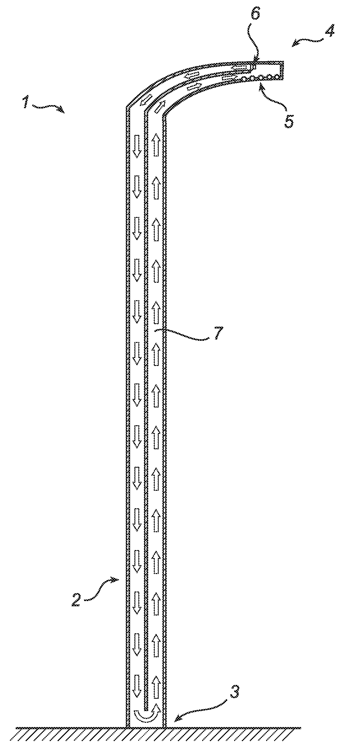
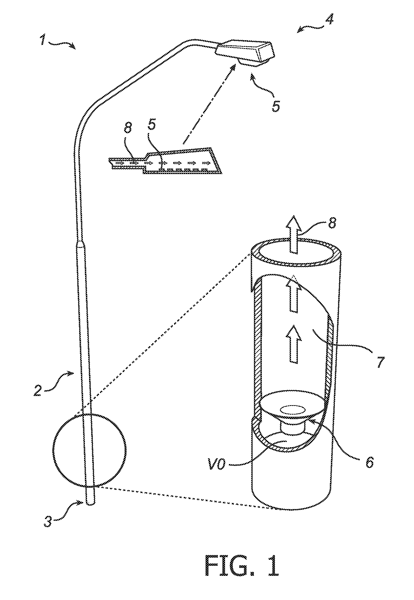
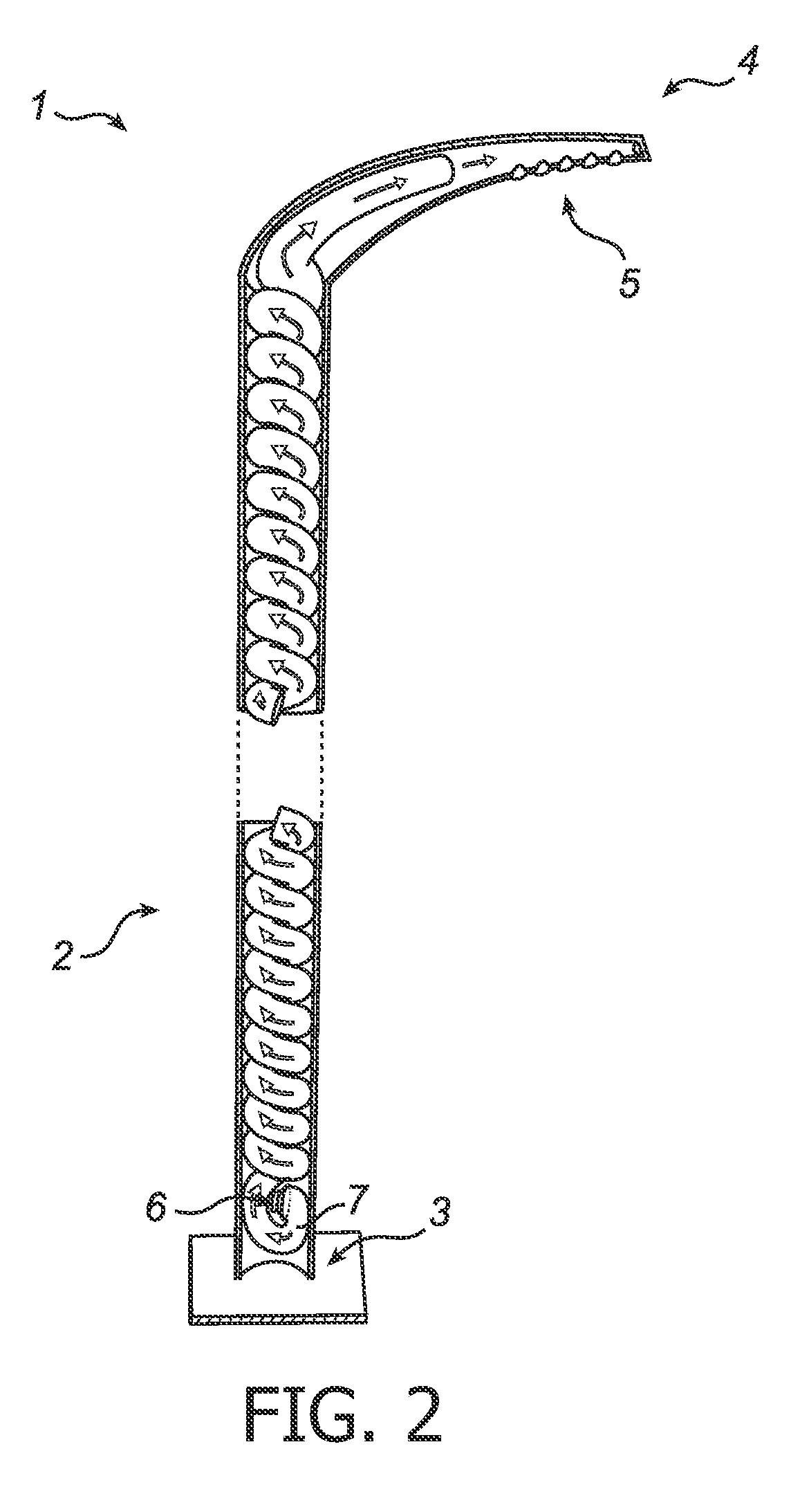
[0027]The illumination device 1 illustrated in FIG. 1 is a street light 1. The suspension structure 2 extends from a support end 3, where the street light 1 is anchored to the ground, to a suspension end 4, where a plurality of light emitting devices 5, here being light emitting diodes (LEDs) 5, are suspended. The suspension structure 2 here has an angled shape to position the LEDs 5 in a desired position. A transducer 6, such as an electrodynamic loudspeaker, is arranged within the suspension structure 2 near the support end 3. A hollow portion of the suspension structure 2 forms a flow guiding structure 7 between the transducer 6 and the LEDs 5. The flow guiding structure 7 may have a rectangular cross-section, but may also have any other cross-section as appropriate. The flow guiding structure 7 may have smooth walls to yield a higher quality factor Q.

[0028]A cavity volume can be provided between the transducer 6 and the flow guiding structure 7. This cavity volume is not require...


PUM


Abstract

An illumination device (1) comprising: at least one light emitting device (5); and a suspension structure (2), suspending the at least one light emitting device (5) in a desired position. Further, the illumination device (1) has a transducer (6), adapted to generate pressure waves at a drive frequency; wherein the suspension structure (2) is utilized as a flow guiding structure (7), having a first end adapted to receive the pressure waves from the transducer, and a second end adapted to generate a pulsating net output flow towards the at least one light emitting device (5), thereby cooling the at least one light emitting device (5). By utilizing the suspension structure itself as flow guiding structure cooling can be integrated in a cost efficient way. Further, no additional space is required to accommodate the flow guiding structure.

Description

FIELD OF THE INVENTION[0001]The present invention relates to pulsating fluid cooling, i.e. cooling where a transducer induces an oscillation creating a pulsating fluid stream that can be directed towards an object that is to be cooled. More particularly the present invention relates to pulsating fluid cooling for an illumination device.BACKGROUND OF THE INVENTION[0002]The need for cooling has increased in various applications due to higher heat flux densities resulting from newly developed electronic devices, being, for example, more compact and / or higher power than traditional devices. Examples of such improved devices include, for example, higher power semiconductor light-sources, such as light-emitting diodes, and large-area devices such as flat TVs and luminaires.[0003]As an alternative to cooling by fans, document WO 2005 / 008348 discloses a synthetic jet actuator and a tube for cooling purposes. The tube is connected to a resonating cavity, and a pulsating jet stream is created...

Claims


Application Information

Patent Timeline
IPC IPC(8): F21S8/00F21K99/00
CPCF04F7/00F21S8/06F21Y2115/10F21V21/32F21W2131/103F21S8/086
Inventor AARTS, RONALDUS MARIALASANCE, CLEMENS JOHANNES MARIANIEUWENDIJK, JORIS ADELBERT MARIAOUWELTJES, OKKE
Owner KONINKLIJKE PHILIPS ELECTRONICS NV
Why Eureka
Try Eureka