Variable stator blade mechanism for turbochargers

a turbocharger and stator blade technology, applied in the field of automobile technology, can solve the problems of limiting the flow and turbine efficiency throughout the range of motion of the vanes within the turbocharger, secondary operations can be time-consuming and costly, vane material or mechanical failure, etc., to achieve the effect of improving turbine efficiency and improving flow

Inactive Publication Date: 2010-07-01
TURBO ENERGY
View PDF10 Cites 8 Cited by
  • Summary
  • Abstract
  • Description
  • Claims
  • Application Information

AI Technical Summary

Benefits of technology

[0023]The objective of the present invention is to provide an arrangement or design for use with a variable nozzle turbocharger that enables improved gas flow distribution even at higher torque when compared to conventional mechanism.
[0024]Another objective of the present invention is to minimize or eliminate unwanted airflow effects within the turbocharger associated with air leakage across the vane, thereby providing improved vane operational reliability and turbocharger efficiency.
[0025]Another objective of the present invention is to improve the flow and in turn increase the turbine efficiency throughout the range of motion.

Problems solved by technology

While such conventional slim or thin airfoil vanes are useful for providing peak aerodynamic efficiency in a VTG, this particular vane design limits the flow and turbine efficiency throughout the range of motion for the vanes within the turbocharger.
Firstly, in order to ensure freely pivoting movement of the vane stem with the opening it is essential that the stem project perfectly perpendicularly from the vane, to thereby avoid undesired binding or otherwise impairment of the vane pivoting movement.
Secondary straightening or machining operations are sometimes necessary to ensure the perpendicularity of the vane shafts, which secondary operations can be both time consuming and costly.
Secondly, this type of vane attachment and pivoting mechanism can produce a high cantilevered load on the vane stem when actuated that can also impair free vane pivoting movement, and that can ultimately result in a vane material or mechanical failure.

Method used


Image

  • Variable stator blade mechanism for turbochargers
  • Variable stator blade mechanism for turbochargers
  • Variable stator blade mechanism for turbochargers

Examples


Embodiment Construction

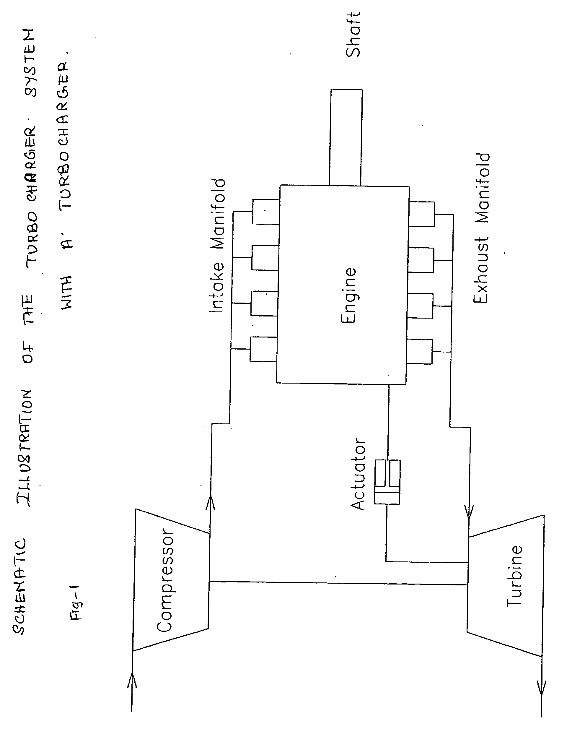
[0041]A turbocharger system according to an embodiment of the present invention will now be described hereinafter with reference to FIGS. 1 to 4.

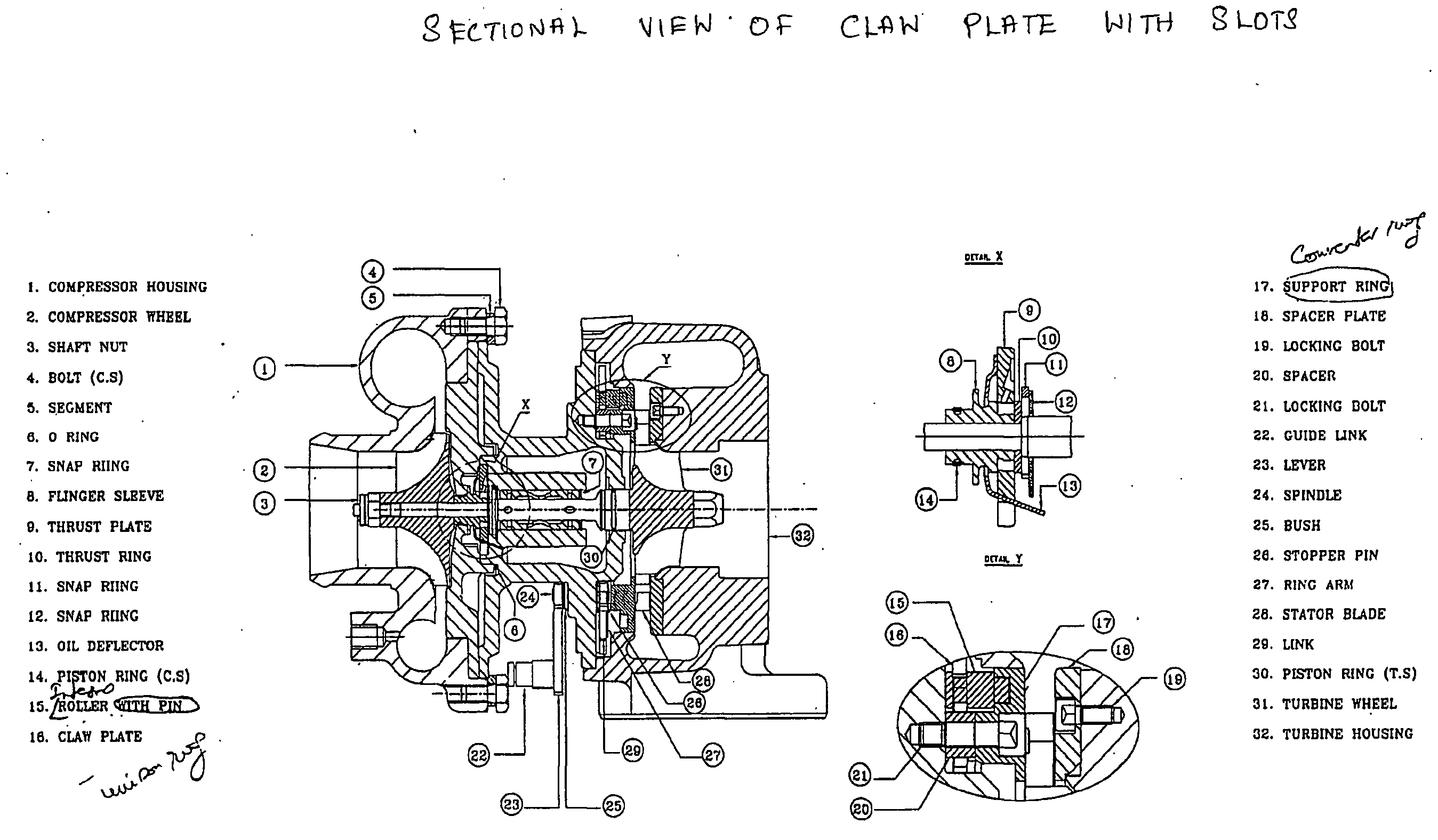
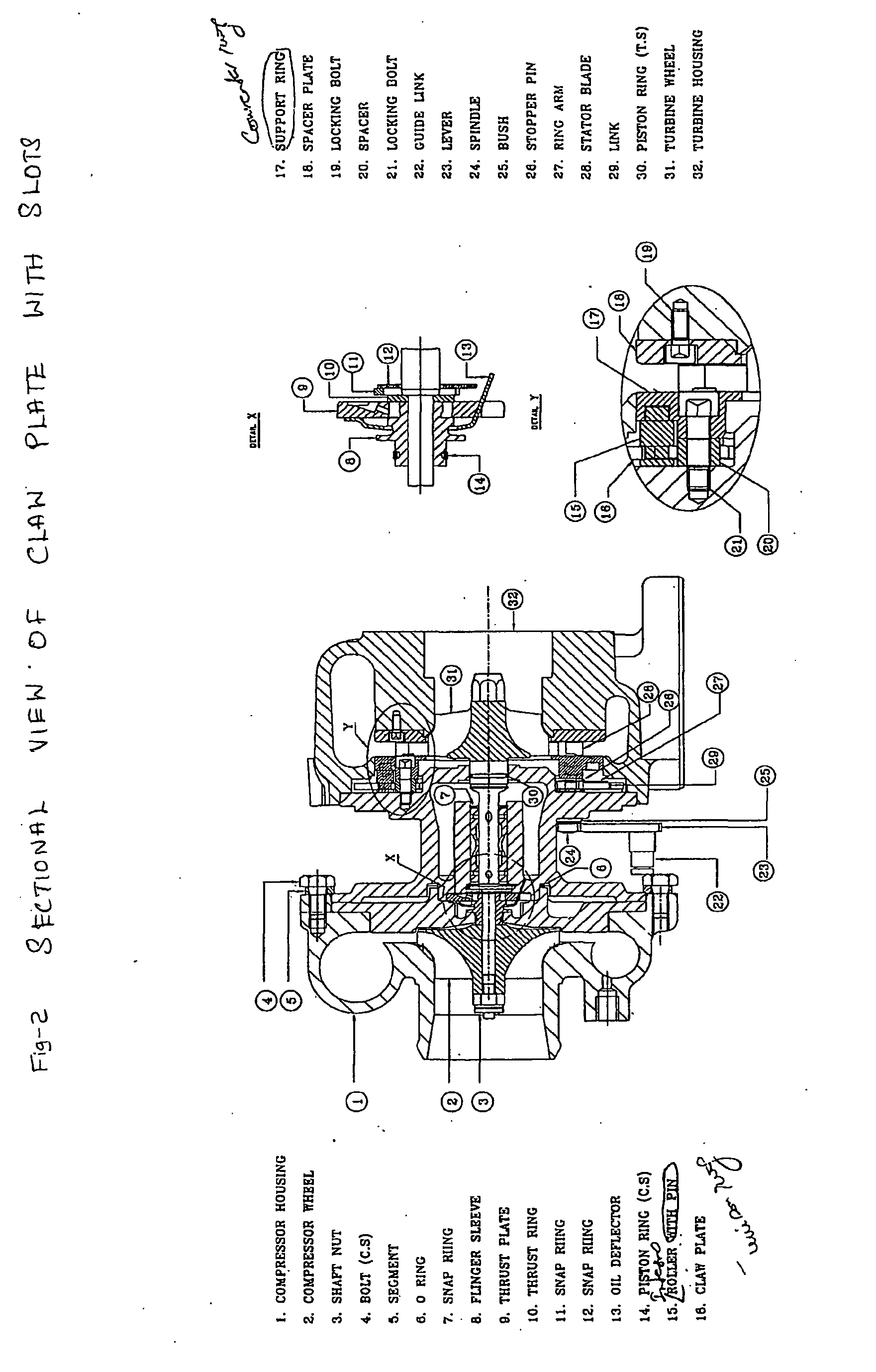
[0042]The first exemplary embodiment of the turbocharger system shown in FIG. 1 has a center housing having a turbine housing attached at one end, and a compressor housing attached at an opposite end. A shaft is rotatably disposed within a bearing assembly contained within the center housing. A turbine or turbine wheel is attached to one shaft end and is carried within the turbine housing, and a compressor impeller is attached to an opposite shaft end and is carried within the compressor housing. The turbine housing has a standard inlet for receiving an exhaust gas stream, and an outlet for directing exhaust gas to the exhaust system of the engine. A volute is connected to the exhaust inlet and an outer nozzle wall is incorporated in the turbine housing casting adjacent the volute. A turbine wheel and shaft assembly is carried within the tu...


PUM


Abstract

A turbocharger with variable turbine geometry comprising of a turbine housing having an exhaust gas inlet and an outlet, a volute connected to the inlet, and a nozzle wall adjacent the volute, carrying a turbine wheel and is attached to a shaft with a plurality of improved aerodynamic profiled stator blades that are disposed within the turbine housing between the exhaust gas inlet and turbine wheel.

Description

FIELD OF INVENTION[0001]The present invention belongs to the field of automobile technology and relates to a mechanical invention consisting of a turbocharger that utilizes variable turbine geometry for maximizing the flow efficiency and improving the performance of turbocharger at higher torque demand condition and reduce the particulate emissions. More particularly the invention relates to a turbocharger in which a turbine housing having an exhaust gas inlet and an outlet, a volute connected to the inlet, and a nozzle wall adjacent the volute, carries a turbine wheel and is attached to a shaft. A plurality of such improved blades are disposed within the turbine housing between the exhaust gas inlet and turbine wheel. The aerodynamic profiled stator blades operate to provide an operational force that improves the efficiency of the turbocharger.BACKGROUND OF INVENTION[0002]Turbochargers for gasoline and diesel internal combustion engines are known devices used in the art for pressur...

Claims


Application Information

Patent Timeline
Patent Type & Authority Applications(United States)
IPC IPC(8): F04D29/56
CPCF01D17/165F02B37/24Y02T10/144F05D2220/40F05D2250/70Y02T10/12
Inventor P.S., KASTURIRANGAN
Owner TURBO ENERGY
Why Eureka
Try Eureka