
Brushless motor for fluid pump and fluid pump using the motor

a brushless motor and fluid pump technology, applied in the direction of piston pumps, magnetic circuit rotating parts, magnetic circuit shapes/forms/construction, etc., can solve the problems of reducing the efficiency of dc motors, reducing electric power, and reducing energy efficiency, so as to overcome the problem of durability, reduce energy efficiency, and excellent operational characteristics

Inactive Publication Date: 2010-07-01
DONG HEE IND
View PDF5 Cites 19 Cited by
  • Summary
  • Abstract
  • Description
  • Claims
  • Application Information

AI Technical Summary

Benefits of technology

[0007]It is an object of the present invention to provide a brushless motor for a fluid pump that allows implementing a fluid pump that overcomes problems of durability and reduction of energy efficiency due to DC motors in the related art and provides excellent operational characteristics, by ensuring a space allowing fluid to flow between a stator and a rotor, and ensuring and maintaining excellent driving characteristics of a motor, and a fluid pump using the brushless motor.
[0012]The present invention provides a brushless motor for a fluid pump that allows implementing a fluid pump that overcomes problems of durability and reduction of energy efficiency due to DC motors in the related art and provides excellent operational characteristics, by ensuring a space allowing fluid to flow between a stator and a rotor, and ensuring and maintaining excellent driving characteristics of a motor, and a fluid pump using the brushless motor.

Problems solved by technology

The DC motors are configured to be supplied with needed electricity for driving a commutator and a brush, in which the durability has a basic problem due to loose contact by wear of the brush and the method of supplying electricity by using contact of the commutator and the brush consumes a large amount of electric power in operation by reducing the efficiency of the DC motors, thereby reducing energy efficiency.

Method used


Image

  • Brushless motor for fluid pump and fluid pump using the motor
  • Brushless motor for fluid pump and fluid pump using the motor
  • Brushless motor for fluid pump and fluid pump using the motor

Examples


Embodiment Construction

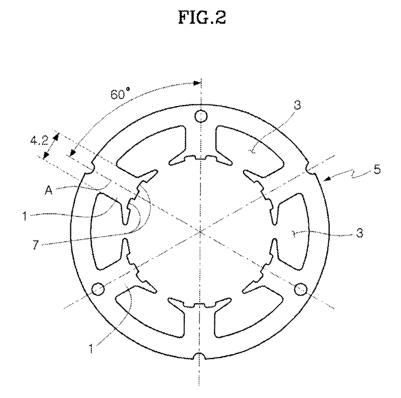
[0028]Referring to FIGS. 1 to 5, a brushless motor according to an embodiment of the present invention includes a stator core 5 having a cross section in which six core shoes 1 symmetrically protrude toward the center of a circle and six slots 3 for winding are formed between the core shoes 1, and two core shoe grooves 7 recessed in the longitudinal direction of the stator core 5 are formed on the inner side of each of the core shoes 1.

[0029]The two core shoe grooves 7 are each formed with a center on a core shoe groove center line B spaced apart at 8.4° from a straight line A passing through the center of the core shoe 1 from the center of the stator core 5, and the width and depth of the core shoe grooves 7 are 1.5 mm and 0.53 mm, respectively.

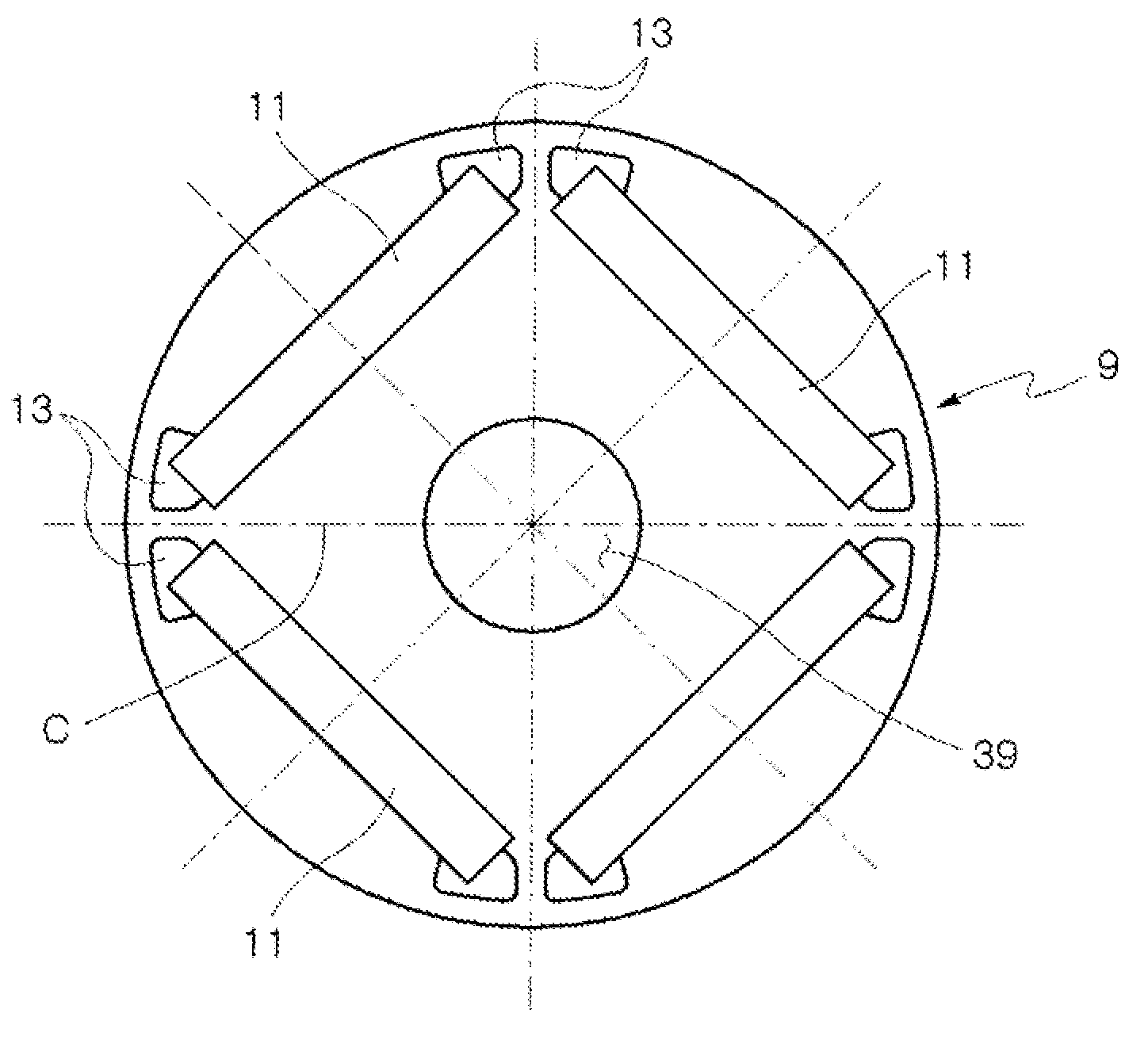
[0030]A rotor core 9, which is inserted in the stator core 5, has permanent magnet holes 11 that are formed in the circumferential direction from the center of the rotor core 9 to be filled with four permanent magnets. Further, bridge holes ...


PUM


Abstract

The present invention provides a brushless motor for a fluid pump that allows implementing a fluid pump that overcomes problems of durability and reduction of energy efficiency due to DC motors in the related art and provides excellent operational characteristics, by ensuring a space allowing fluid to flow between a stator and a rotor, and ensuring and maintaining excellent driving characteristics of a motor, and a fluid pump using the brushless motor.

Description

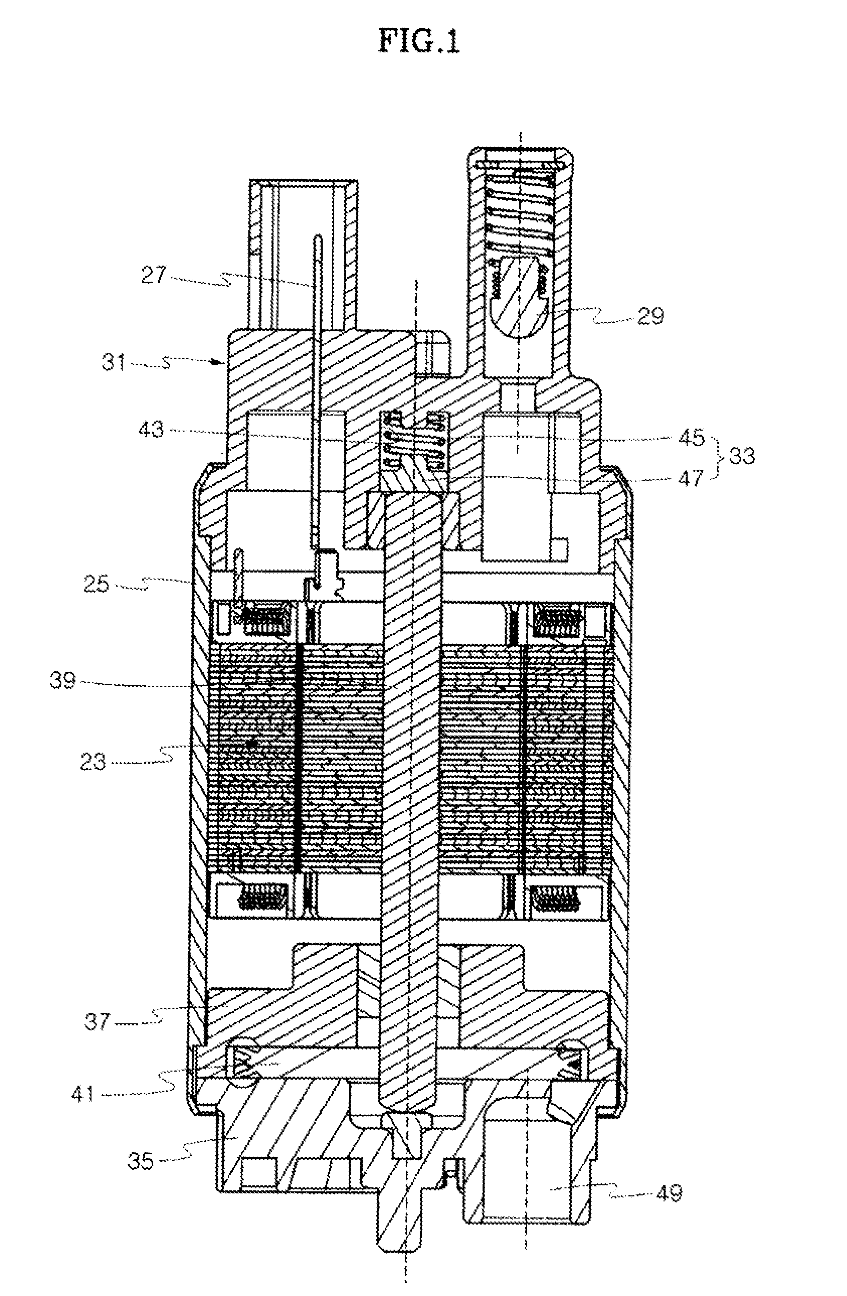
BACKGROUND OF THE INVENTION[0001]1. Field of the Invention[0002]The present invention relates to a brushless motor, in more detail, a structure of a brushless motor that is used in a fluid pump pumping and discharging fluid, and a fluid pump using the brushless motor.[0003]2. Description of the Related Art[0004]In fluid pumps pumping and discharging fluid, fuel pumps that are mounted in a fuel tank of vehicles and pump fuel have been known, and typical DC motors equipped with a common commutator have been used in the fuel pumps in the related art.[0005]The DC motors are configured to be supplied with needed electricity for driving a commutator and a brush, in which the durability has a basic problem due to loose contact by wear of the brush and the method of supplying electricity by using contact of the commutator and the brush consumes a large amount of electric power in operation by reducing the efficiency of the DC motors, thereby reducing energy efficiency.[0006]Brushless motors...

Claims


Application Information

Patent Timeline
Patent Type & Authority Applications(United States)
IPC IPC(8): F04D13/06H02K1/27
CPCF04D5/002H02K1/276H02K5/12H02K7/14H02K29/03F04D13/06H02K1/16H02K1/27
Inventor NOH, JONGSANGCHA, JONGGEUNLEE, JONGMAN
Owner DONG HEE IND
Learn More