
Method for selecting an effective angle of reception of a directional antenna of a receiver node, corresponding storage means and receiver node

a receiver node and effective angle technology, applied in direction finders using radio waves, wireless commuication services, instruments, etc., can solve the problems of inability to communicate between these two nodes, limited range of about 10 meters, complex and costly, etc., and achieve the greatest possible divergence

Active Publication Date: 2010-07-01
CANON KK
View PDF8 Cites 4 Cited by
  • Summary
  • Abstract
  • Description
  • Claims
  • Application Information

AI Technical Summary

Benefits of technology

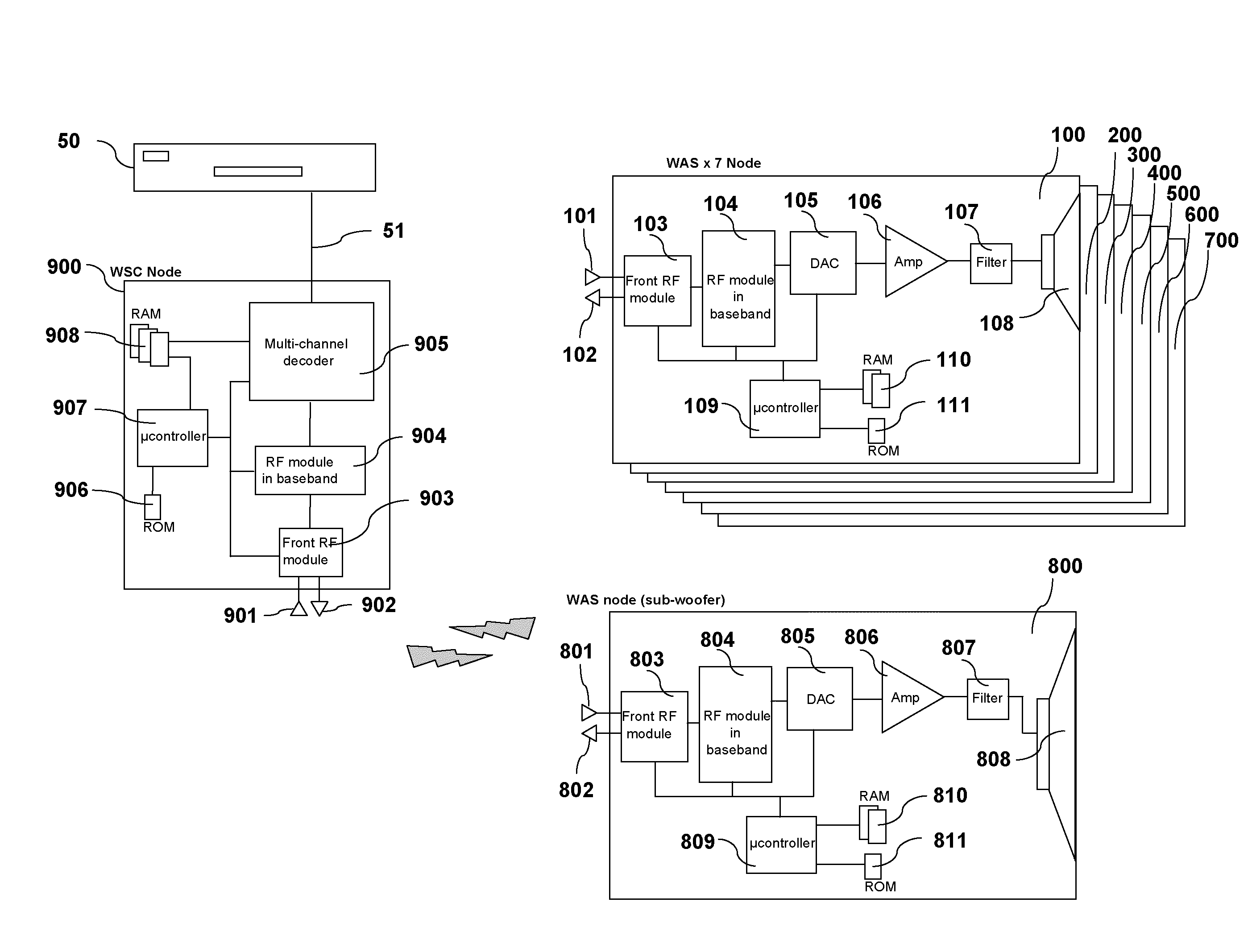
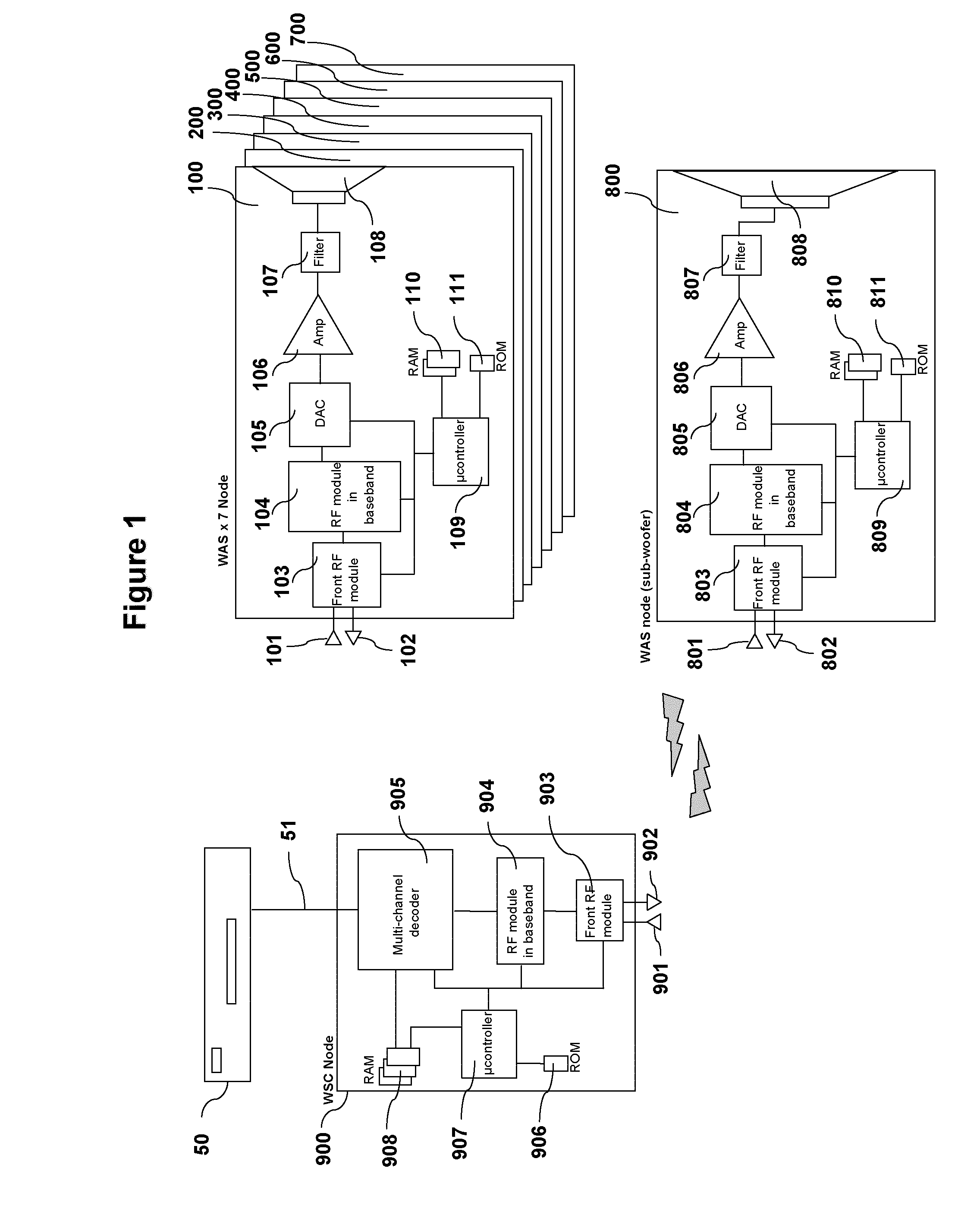
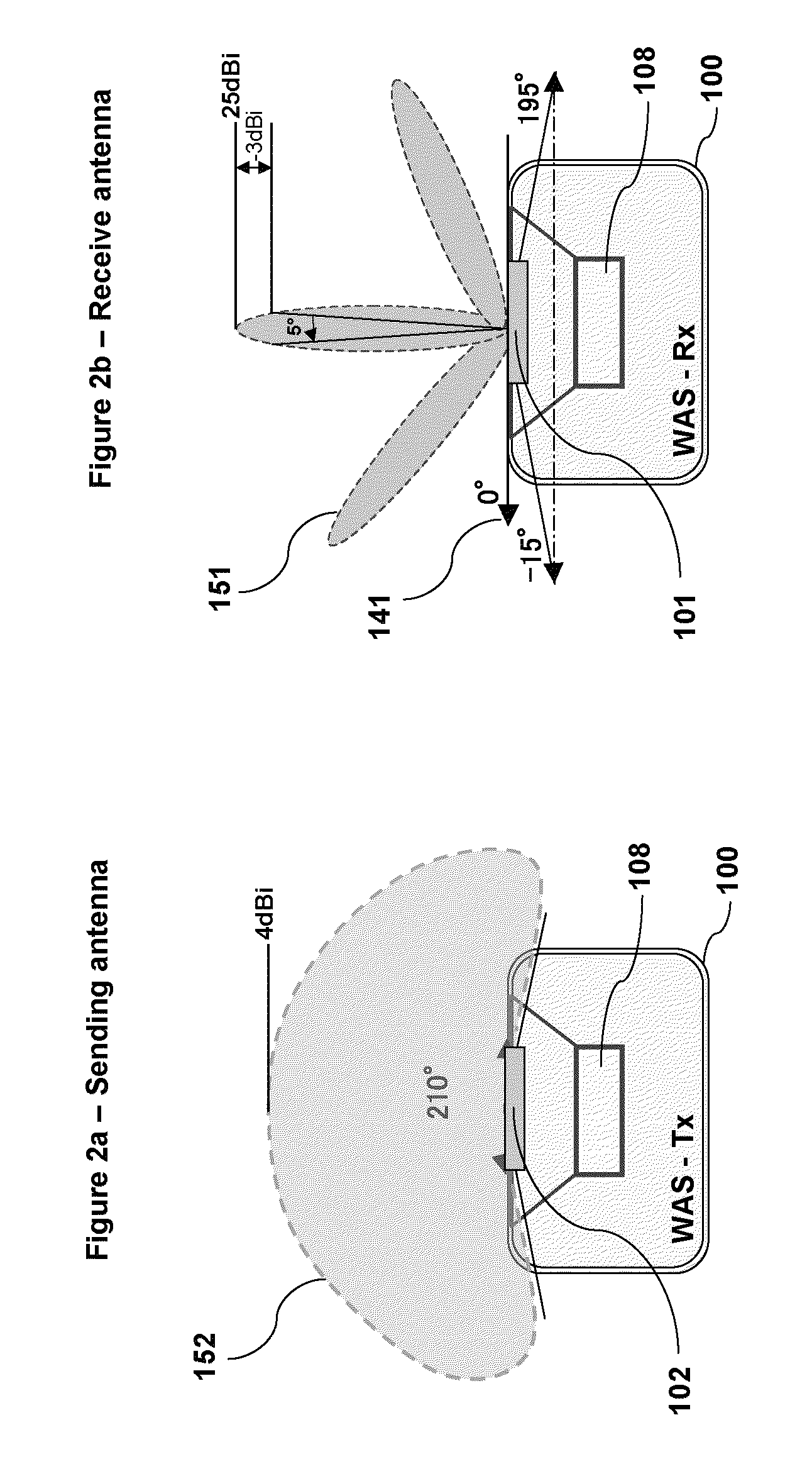
[0043]Thus, an embodiment of the invention proposes the selection of an effective angle of reception to communicate with a given sender node as a function of an angular divergence. More specifically, the general principle of the invention consists in choosing the effective angle of reception as a function of the proximity between the values of the possible angles of reception to communicate with a given sender node and values of effective angles of reception enabling communication with other (second) sender nodes of the network. An embodiment of the invention can therefore be used to improve the coverage of the network since the receiver node selects values of effective angles of reception which are distant from one another. Thus, the technique of the invention can be used to prevent an obstacle situated in a given communications path from disturbing the other communications paths of the receiver node. These communications paths are angularly divergent from the communications path disturbed by the obstacle.
[0055]Thus, the receiver node uses the effective angles of reception which are at a maximum distance from one another. Thus, the spatial diversity in the network is maximized.
[0072]Advantageously said means for obtaining obtain, as an effective angle of reception relative to said second emitter node, the angle of reception associated with said second emitter node making it possible to have the greatest possible divergence with the effective angle of reception.

Problems solved by technology

Indeed, since air attenuates millimeter RF waves (following physical laws well-known to those skilled in the art), the range is limited to about 10 meters.
In such a situation, any communication between these two nodes is impossible.
First of all, this technique calls for the implementation of a main radio channel, a secondary radio channel and a bit error rate measurement mechanism for measuring the bit error rate on the main radio channel. This is particularly complex and costly.
The bit error rate measurement mechanism therefore proves to be costly in terms of computation power and electrical power supply.
Furthermore, the switching to new antenna orientations may temporarily downgrade the quality of service of the application.
However, for networks having a limited number of nodes, it is not optimal.
Thus, in certain configurations, when a shadowing comes into play on one of the radio paths, it may happen that certain nodes do not receive a sufficient number of copies of the same data to detect and correct the errors reliably.
Consequently, another major drawback of classic mesh technique lies in the fact that a same obstacle can disturb several direct lines of sight of a node (if this node uses antenna orientation angles that are close to each other), thus harming the overall quality of service of the network.

Method used


Image

  • Method for selecting an effective angle of reception of a directional antenna of a receiver node, corresponding storage means and receiver node
  • Method for selecting an effective angle of reception of a directional antenna of a receiver node, corresponding storage means and receiver node
  • Method for selecting an effective angle of reception of a directional antenna of a receiver node, corresponding storage means and receiver node

Examples


first embodiment

[0231]The algorithm presented with reference to FIG. 9 is a first non-restrictive embodiment of the present invention. According to this algorithm, the choice of the antenna angles is based on a predetermined angular proximity threshold. In this first embodiment, the first combination of antenna angles identified as responding to the criterion of angular proximity is selected.

second embodiment

[0232]In a second embodiment, an algorithm based on the selection of the antenna angles having the maximum angular divergence can be used. In this embodiment, the step 17 would consist of recording the sum of the absolute values of angular divergence for all the combinations of antenna angles provided (allocated). Ultimately, the combination of antenna angles corresponding to the sum of the absolute values giving the maximum result would be chosen.

[0233]For example, let Si,j,k be the sum of divergence values for a given combination (i,j,k). We then get:

Si=1, j=1, k=1=(|A1−B1|+|A1−C1|+|C1−B1|)

S1=1, j=1, k=2=(|A1−B1|+|A1−C2|+|C2−B1|)

Si=2, j=2, k=2=(|A2−B2|+|A2−C2|+|C2−B2|)

[0234]The combination of antenna angles (i,j,k) chosen will be the one having the corresponding Si,j,k with the greatest value.

third embodiment

[0235]In a third embodiment, an algorithm based both on a predetermined angular proximity threshold and on the selection of the antenna angles having the maximum angular divergence can be chosen. In this embodiment, the step 17 would in a first stage consist in identifying all the combinations of antenna angles for which the absolute values of the angular divergences are greater than the angular proximity threshold. Then, in a second stage, the step 17 would consist in recording the sum of the absolute values of the angular divergences of each of the combinations of antenna angles identified. Ultimately, the combination of antenna angles corresponding to the sum of the absolute values giving the maximum results would be chosen.

[0236]In resuming the above example, this amounts to choosing, in this third embodiment, the combination of antenna angles (i,j,k) having the Si,jk values corresponding to the greatest of the combinations of angles for which the divergences and |Ai−Bj|, |Ai−Ck...


PUM


Abstract

It is proposed a method for selecting an effective angle of reception of a directional antenna of a receiver node, the receiver node belonging to a wireless communications network comprising a plurality of emitter nodes.The method is implemented by the receiver node and comprises steps of:determining at least two possible angles of reception associated with a first emitter node, andfor each of said at least two possible angles of reception, determining a difference between that angle and an angle of reception associated with a second emitter node different from said first emitter node, and selecting the effective angle of reception from among said at least two possible angles of reception associated with said first emitter node as a function of the determined differences.

Description

1. FIELD OF THE DISCLOSURE[0001]The field of the disclosure is that of wireless personal area networks (WPANs) or home communications networks, for example of the mesh type, comprising a plurality of nodes each having for example a reception antenna and an emission antenna.[0002]The disclosure pertains especially but not exclusively to such networks which use millimeter wave radio-frequency (or RF) bands, namely wavebands around 60 GHz.2. BACKGROUND OF THE DISCLOSURE[0003]Wireless applications are now increasingly numerous. Such applications (for example of the audio and / or video type) require very high bit rates (of the order of one gigabit per second) working up to distances of about 10 meters.[0004]60 GHz radio transmission systems are particularly well suited to data transmission at very high bit rates within a limited radius. Indeed, since air attenuates millimeter RF waves (following physical laws well-known to those skilled in the art), the range is limited to about 10 meters...

Claims


Application Information

Patent Timeline
IPC IPC(8): H04B7/00
CPCH04B7/0408H04W72/046H04W84/18
Inventor LORGEOUX, MICKAELCAILLERIE, ALAIN
Owner CANON KK
Learn More