Control method and control system for manipulator

a multi-jointed manipulator and control method technology, applied in the field of multi-jointed manipulator control, can solve the problems of inability to work for intended operations depending on the environment, inability to uniquely solve, and inability to control, so as to achieve easy and flexible control, high degree of freedom, and the effect of manipulator control

Inactive Publication Date: 2010-07-01
PANASONIC CORP
View PDF5 Cites 38 Cited by
  • Summary
  • Abstract
  • Description
  • Claims
  • Application Information

AI Technical Summary

Benefits of technology

[0092]According to the control method and the control system of manipulators in the present invention described above, since the position control for a control target (a specified range including a control target) is performed independently on a joint-to-joint basis, there occurs neither the problem that the control command value involved in inverse kinematics cannot be uniquely determined nor the problem due to large quantities of computations, even in a manipulator having redundancy or nonlinear drive elements. Thus, the position control of the manipulator can be carried out with reliability.
[0093]Also, since there is no need for setting constraint conditions for the computation of inverse kinematics or for limiting the degree of freedom, the control can be carried out while a high degree of freedom is main

Problems solved by technology

However, since there are some problems, for example, that Equation (2) cannot be uniquely solved for redundant control systems, other calculation methods may be used, in some cases, instead of Equation (2) (see, e.g., Patent Documents 1 and 2).
However, the conventional control methods, when applied to manipulators that perform operations demanding higher degrees of freedom, encounter the following issues.
The conventional method using inverse kinematics, although applicable to manipulators which are nonredundant and have no nonlinear elements, yet may be incapable of working for intended operations depending on environments.
On the other hand, with redundancy or nonlinear drive elements incorporated for enhancement of the degree of freedom for operations, the inverse kinematic equation, Equation (2), becomes too complicated to uniquely solve, which may lead, in some cases, to an impossibility of control or an enormous quantity of computations that makes it impossible to fulfill real-time control.
However, since the degree of freedom is limited by the constraint conditions in one aspect, there is a possibility that the workability of the manipulator may be limited.
However, without any proper setting of parameters or teaching data, it can occur that the training takes m

Method used


Image

  • Control method and control system for manipulator
  • Control method and control system for manipulator
  • Control method and control system for manipulator

Examples


first embodiment

[0126]Herein below, a control system of a manipulator according to a first embodiment of the present invention, as well as its control method, will be described with reference to the accompanying drawings.

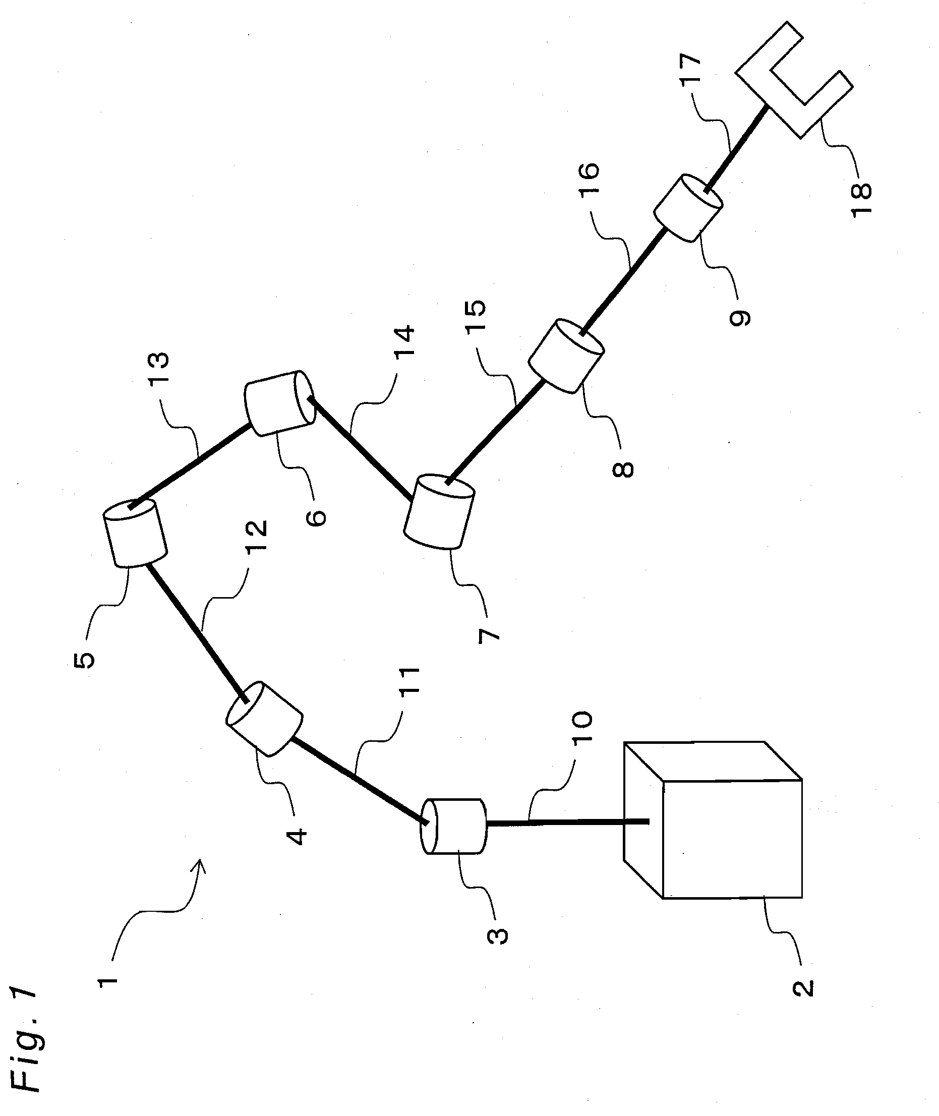
[0127]FIG. 1 is a schematic view of a manipulator according to a first embodiment of the invention. As shown in FIG. 1, the manipulator 1 comprises seven joint axes 3-9, eight links 10-17 for connecting the joint axes to one another, a base 2 for supporting the joint axes 3-9 in series via the link 10, and a hand (end portion or hand end) 18 connected to a forward end of the series-connected joint axes 3-9. The manipulator 1 is enabled to make the hand 18 positioned at a control target by operations of the respective joint axes 3-9.

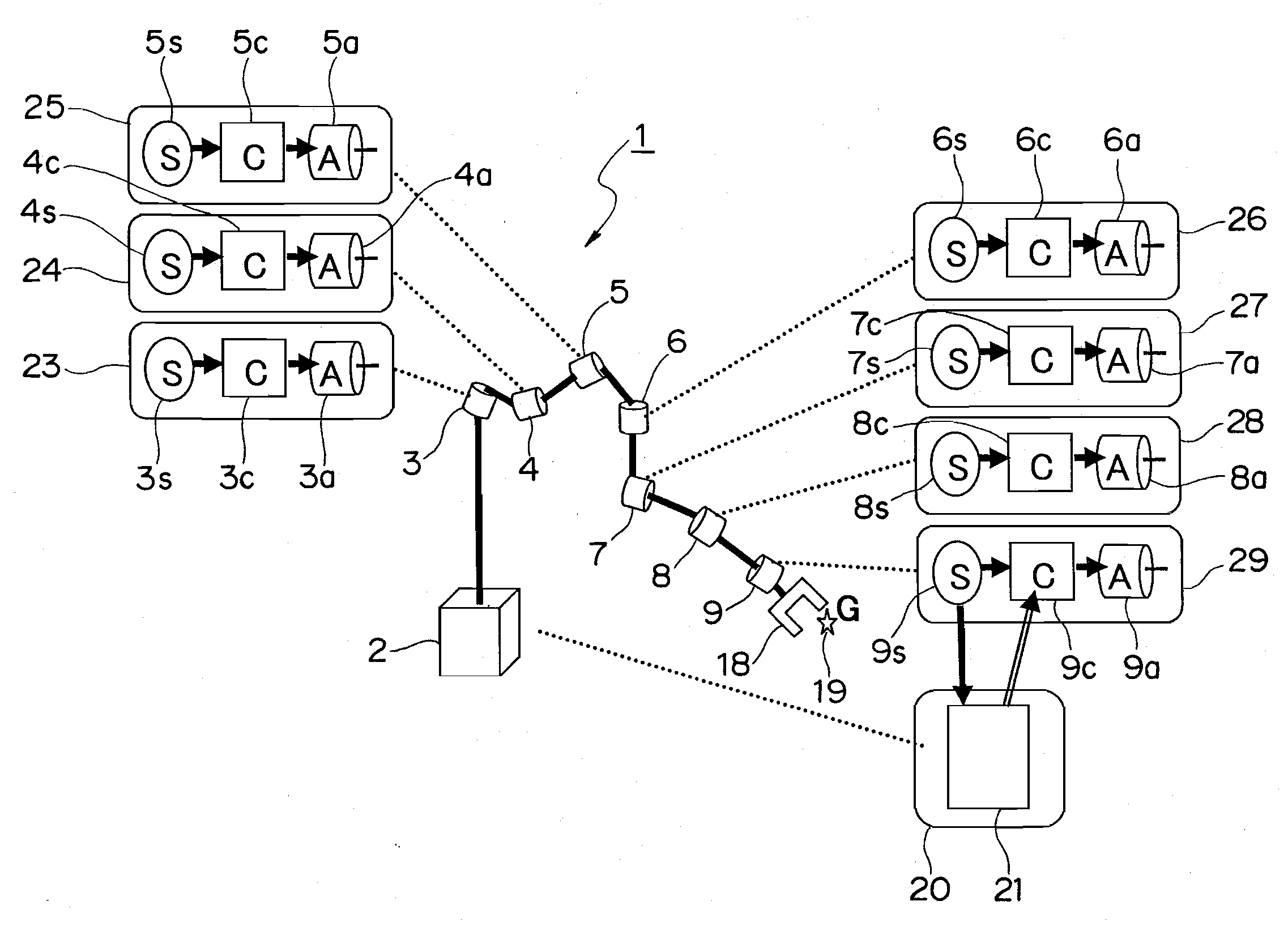
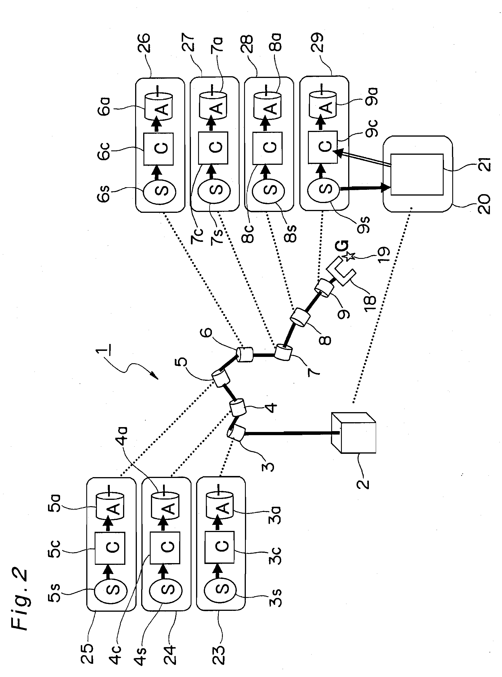
[0128]FIG. 2 is a schematic view of a control system of the first embodiment. The control system performs operation control for the respective joint axes 3-9 to exert control for making the hand 18 of the manipulator 1 positioned at a control target 19 (...

second embodiment

[0168]The present invention is not limited to the foregoing first embodiment, and may be embodied in other various modes. A manipulator control method according to a second embodiment of the invention is described below.

[0169]In actual scenes of use of the manipulator, there is a need for flexible management of various working operations. For this purpose, although the configuration or joint count of the manipulator may be changed depending on the working operation, yet the control method of this second embodiment can be exploited in order to eliminate the need for preparing programs or rewriting programs in accordance with the configuration or joint count of the manipulator. As a result of this, even changes in the configuration or joint count of the manipulator can be managed only by parameter changes, allowing the manipulator to be added and changed to a robot or the like for immediate use in a plug-and-play like fashion.

[0170]Hereinbelow, a method for achieving addition and chan...

third embodiment

[0188]Next, a control method by a manipulator control system according to a third embodiment of the invention is described with reference to a schematic view of the manipulator control system shown in FIG. 14.

[0189]As shown in FIG. 14, the control system of a manipulator 201 in this third embodiment includes joint control sections 223-229 for controlling their respective joint axes 3-9, independently of the other joint axes, and a total evaluation section 220 for performing evaluation of the total state or the like of the manipulator 201.

[0190]Each of the joint control sections 223-229 includes a measuring device (9s etc.) having an encoder or other sensor mounted on each of the joint axes 3-9, an actuator (9a etc.) for driving its corresponding joint axis, and a control computation processing device (9c etc.) for calculating a control command value for the actuator based on input information. The total evaluation section 220 includes a total evaluation processing device 221.

[0191]T...


PUM


Abstract

In a control method of a multi-jointed manipulator, the manipulator is controlled through a process to transmit a difference between an end position of the manipulator and a target position to the joint axes, and a process to adjust joint displacements and joint velocities of the joint axes independently of one another of the joint axes based on the difference, these processes being repeated until the end position coincides with the target position. By such a manipulator control method, there can be realized position control which is robust against ambient environments and which is easy to achieve even with redundancy or nonlinear drive elements involved.

Description

BACKGROUND OF THE INVENTION[0001]1. Technical Field[0002]The present invention relates to a technique of controlling a multi-jointed manipulator.[0003]2. Description of Related Art[0004]Multi-jointed manipulators have been used in robot arms or the like of industrial or consumer use. Various techniques are already available in association with position control for such manipulators.[0005]As an example, there is a technique using inverse kinematics in which displacements or driving forces of respective joint axes for achieving specific end-point position of a manipulator are determined by computation of inverse kinematics to allow the control to be performed based on the resulting displacement or driving forces.[0006]An example of this related art technique using inverse kinematics is explained with reference to FIGS. 19 and 20. FIG. 19 is a view showing an outline of a manipulator control method according to a related art, and FIG. 20 is a control processing flowchart of a manipulat...

Claims


Application Information

Patent Timeline
IPC IPC(8): B25J9/10
CPCB25J9/06B25J9/1643
Inventor OKAMOTO, TAMAO
Owner PANASONIC CORP
Why Eureka
Try Eureka