Torque coupling assembly

a coupling assembly and torque technology, applied in the direction of couplings, wheel-axle combinations, interlocking clutches, etc., can solve the problems of chain falling off the front sprocket as well, affecting the operation, and likely to be required to operate frequently, etc., to achieve easy assembly, easy insertion and/or removal, and easy assembly

Inactive Publication Date: 2010-07-08
SCHLANGER RAPHAEL
View PDF7 Cites 25 Cited by
  • Summary
  • Abstract
  • Description
  • Claims
  • Application Information

AI Technical Summary

Benefits of technology

[0019]The present invention obtains many advantages. It is an advantage of the present invention to provide a decoupling hub assembly whereby the rotatably driven or driving assembly may be easily assembled and easily uninstalled or removed from its opposing driven or driving assembly, and including torque coupling between these two elements. As applied to bicycle wheels, this advantage translates to an arrangement where the driven rear wheel may be easily and simultaneously disassembled from the corresponding drive sprocket assembly and the bicycle frame. In the application described herein, the present invention relates to the rear hub of a bicycle wheel. However, the basic principles of this invention may alternatively be applied to a wide range of power transmission applications that are known throughout industry.
[0020]The present invention is particularly applicable to a decoupling engagement mechanism between the one-way clutch assembly of the bicycle sprocket assembly, commonly referred to as the freehub body, and the rear hub shell, which is the outer rotating member of the rear hub assembly. Thus, when the rear hub is uninstalled or removed from the bicycle frame, the freehub body, and its associated sprockets, remain attached to the frame. Since the sprockets are now still in place, the chain remains under tension with the rear wheel removed. Thus, all of the problems associated with the dangling chain and the complex reassembly are eliminated. This greatly reduces the difficulty involved in replacement of the rear wheel and also solves the shortcomings previously described that are associated with the conventional hub assembly. Furthermore, the chain may remain engaged with whichever sprocket had previously been selected, providing particular benefit in racing conditions where time is critical.
[0021]The present invention may utilize ramped lead-in geometry, shielding geometry, radial self-piloting geometry, and / or circumferentially self-nesting geometry. These geometry features serve to guide and align the hub upon removal and / or reinstallation of the wheel to the frame, minimizing the potential for mating components of the driving and driven elements to snag and / or interfere with each other during removal and / or installation of the wheel. In comparison with other decoupling hub designs, these geometry features make the removal and / or reinstallation of the wheel much more user-friendly and easy. Further, this also minimizes any special skills and dexterity involved in the removal and / or reinstallation of the wheel.
[0022]In the ensuing descriptions, the term “axial” refers to a direction parallel to the centerline of the wheel axle and the term “radial” refers to a direction perpendicular to the centerline of the wheel axle.
[0023]In contrast to the aforementioned decoupling arrangements that employ a slideable torque coupling element, the present invention provides a far simpler mechanism without the expensive precision components and without the difficult sealing challenges.
[0024]Further, the present invention outlines several features to optimize the functionality of the decoupling hub assembly, including means to control axial spacing and provide a solid axial stack-up of the assembly, including control shaft arrangements to aid in ease of assembly, including engagement tooth interactions to provide blocking and self-energizing engagement, including ramped lead-in geometry to provide self-aligning assembly of the system as well as camming or wedging to aid in controlling dropout spacing during assembly, including shielding systems to allow for smooth assembly without challenges relating to tangling of face teeth, including detent and spring-biased control shaft systems that optimize functionality and ease-of-use, and including several other advantageous designs as outlined herein.

Problems solved by technology

Such an operation is likely to be required frequently.
The chain now tends to dangle and drag on the ground, picking up contaminants and spreading grease onto the surfaces that it comes in contact with.
The lack of chain tension also invariably causes the chain to fall off of the front sprockets as well and become tangled.
Reassembly of the wheel to the frame is also problematic, requiring a great degree of skill and dexterity.
This is often a daunting and messy task for most cyclists.
While removal of the bicycle's front wheel is a relatively easy operation that may be contemplated by the novice cyclist, removal of the rear wheel is considered to be an intimidating procedure better left to the professional or to an enthusiast fluent in the mechanics of the bicycle.
Further, in a bicycle race, every second is are precious.
Such an arrangement adds difficulty to the procedure of disassembly of the wheel from the frame and leaves the frame vulnerable to overstress in this spreading process.
This is particularly true if the axial overlap is excessive and if the interface geometry of the mating elements causes the driving and driven elements to snag and / or interfere with each other during removal and / or installation of the wheel.
While such designs are intended to be more user friendly than conventional hubs, this has not been the case, since the dropouts must be spread simultaneous with insertion of the hub.
Further, the poor design of the aforementioned mating interface serves to make assembly and removal of the wheel a tedious and frustrating experience.
This telescoping type of configuration involves relatively high complexity with a multitude of expensive precision components.
Furthermore, these slideable components create difficult sealing challenges to function in the harsh environment that bicycles are commonly subject to.

Method used


Image

  • Torque coupling assembly
  • Torque coupling assembly
  • Torque coupling assembly

Examples


Embodiment Construction

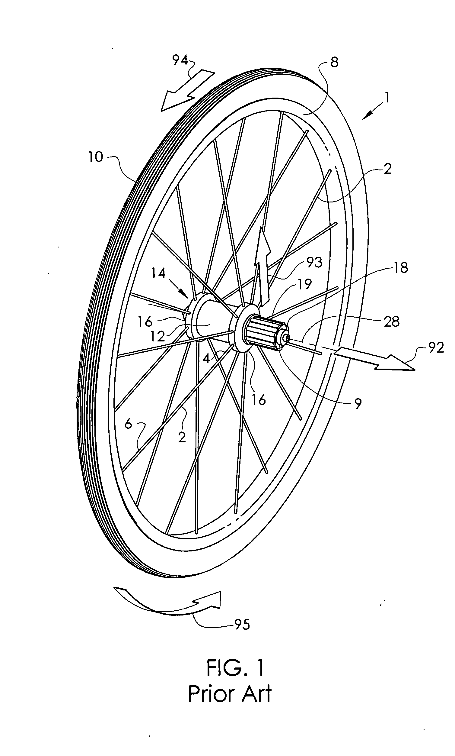
[0054]FIG. 1 describes the basic configuration of an exemplary prior art vehicle wheel, in particular, a bicycle wheel 1, as well as a description of the direction conventions used throughout this disclosure. The hub shell 14 is rotatable about the axle 9 and includes at least two axially spaced hub flanges 16, each of which include a means for connecting with the spokes 2. The axial axis 28 is the axial centerline of rotation of the bicycle wheel 1. The hub flange 16 may be contiguous with the hub shell 14 or it may be separately formed and assembled to the hub body 12 portion of the hub shell 14. The spokes 2 are affixed to the hub flange 16 at their first end 4 and extend to attach the rim 8 at their second end 6. The tire 10 is fitted to the outer periphery of the rim 8. The freehub body 18 is rotationally coupled to hub shell 14 via a one-way clutch and also includes splines 19, which are adapted to receive the drive sprocket(s) (not shown). The wheel of FIG. 1 is generic and m...


PUM


Abstract

A torque coupling assembly that includes a rotationally driving assembly with a rotationally fixed driving axle element and a rotatable driving shell element, and an axial axis of rotation; a rotationally driven assembly, with a rotationally fixed driven axle element and a rotatable driven shell element, and an axial axis of rotation; a frame element with at least two axially spaced mounting elements for mounting of said torque coupling assembly; where the rotatable driving shell includes an axial projection anchored thereto, with a tip portion located axially distal from the driving shell and a root portion axially proximal to the driving shell, and an axially relieved portion circumferentially adjacent the axial projection; where the rotatable driven shell includes an axial projection anchored thereto, with a tip portion located axially distal from the driven shell and a root portion axially proximal to the driven shell, and an axially relieved portion circumferentially adjacent the axial projection; where, in an assembled or installed position, the driving assembly and the driven assembly are both connected to the frame the axial projection of the driving shell is aligned to engage the axial projection of the driven shell with an axial overlie engagement to rotatably transmit torque between the driving shell and the driven shell; where, in a removed or uninstalled position, one of the driving assembly and the driven assembly may be displaced in a generally radial direction relative to the frame and the other of the rotational driving assembly and the rotational driven assembly; where at least one of the driving assembly and the driven assembly includes ramped lead-in geometry adjacent the axial projection(s); and optionally where at least one of the driving assembly and the driven assembly includes shielding geometry adjacent and the axial projection, where the shielding geometry extends to axially overlap at least a portion of the axial projection.

Description

CROSS-REFERENCE TO RELATED APPLICATION[0001]This application claims priority of U.S. provisional patent application 61 / 204,130, filed Jan. 2, 2009, and entitled “TORQUE COUPLING ASSEMBLY”.BACKGROUND[0002]1. Field of the Invention[0003]The present invention relates to torque coupling arrangements between two axially adjacent rotatable assemblies that both rotate about a collinear axis and, as shown in the instant embodiments, the present invention also relates to the attachment of a vehicle wheel to its mount frame, more specifically the attachment of a driven bicycle wheel to the driving assembly in conjunction with the attachment to the frame.[0004]2. Discussion of Prior Art[0005]Heretofore, the complete rear drive sprocket assembly is assembled to remain affixed to the rear wheel hub. Thus the rear drive sprocket or sprockets remain attached to the rear wheel when the rear wheel is removed from the frame. Whenever the wheel or tire is damaged, or when the bicycle must be taken apa...

Claims


Application Information

Patent Timeline
Patent Type & Authority Applications(United States)
IPC IPC(8): F16D41/24
CPCF16D41/36F16D2300/12
Inventor SCHLANGER, RAPHAEL
Owner SCHLANGER RAPHAEL
Why Eureka
Try Eureka