Controlled environment fastener head painting device and method

Active Publication Date: 2010-07-08
THE BOEING CO
View PDF35 Cites 43 Cited by
  • Summary
  • Abstract
  • Description
  • Claims
  • Application Information

AI Technical Summary

Benefits of technology

[0012]The painting apparatus may be provided in a relatively small size to facilitate transporting thereof to different locations such as different locations of a manufacturing or assembly facility. In addition, by providing the painting apparatus in a relatively small size, the temperature and humidity level of an interior environment of the painting apparatus may be easily controlled and maintained such as by using a pressurized air source. Even further, the relatively small size may simplify construction and reduce the cost of the painting apparatus as compared to relatively large, stationary paint booths and curing ovens whic

Problems solved by technology

Considering the large quantity of subassemblies that make up a commercial aircraft and the overall size of such aircraft, the quantity of fasteners that must be provided in a pre-painted condition may be relatively large.
Difficulties in meeting film thickness requirements can occur as a result of inconsistencies during manual application of paint.
Furthermore, inappropriate temperature and humidity levels during application of the paint and during curing of the paint can result in inconsistencies in adhesion and appearance (e.g., runs, wrinkles) of the painted fastener heads.
As a result of such stringent requirements, the number of subcontractors that are qualified to provide painting services may be limited.
The limited number of qualified subcontractors may impact the ability to provide the large quantity of pre-painted fasteners on schedule.
Difficulties in meeting schedule may be ex

Method used


Image

  • Controlled environment fastener head painting device and method
  • Controlled environment fastener head painting device and method
  • Controlled environment fastener head painting device and method

Examples


Embodiment Construction

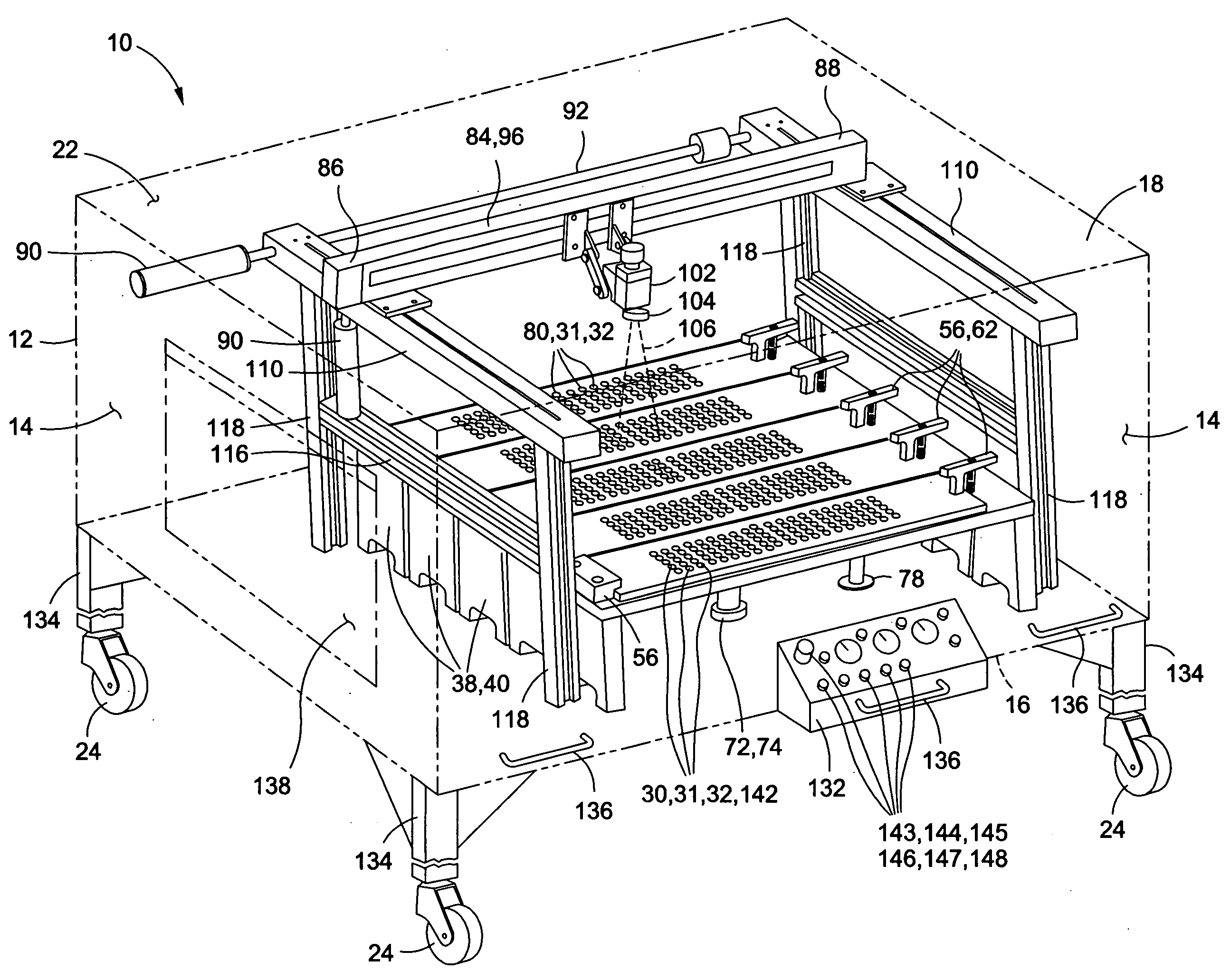
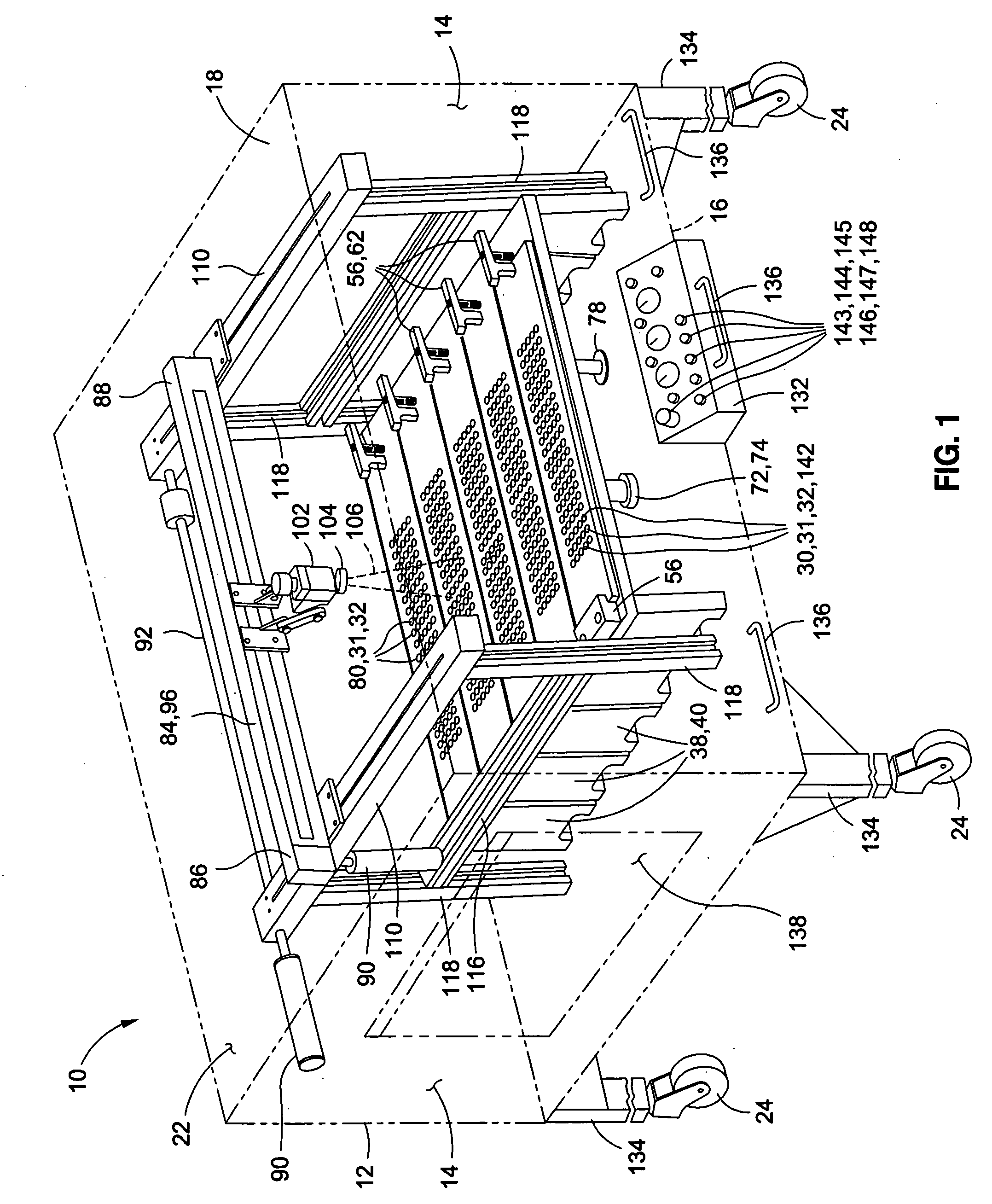
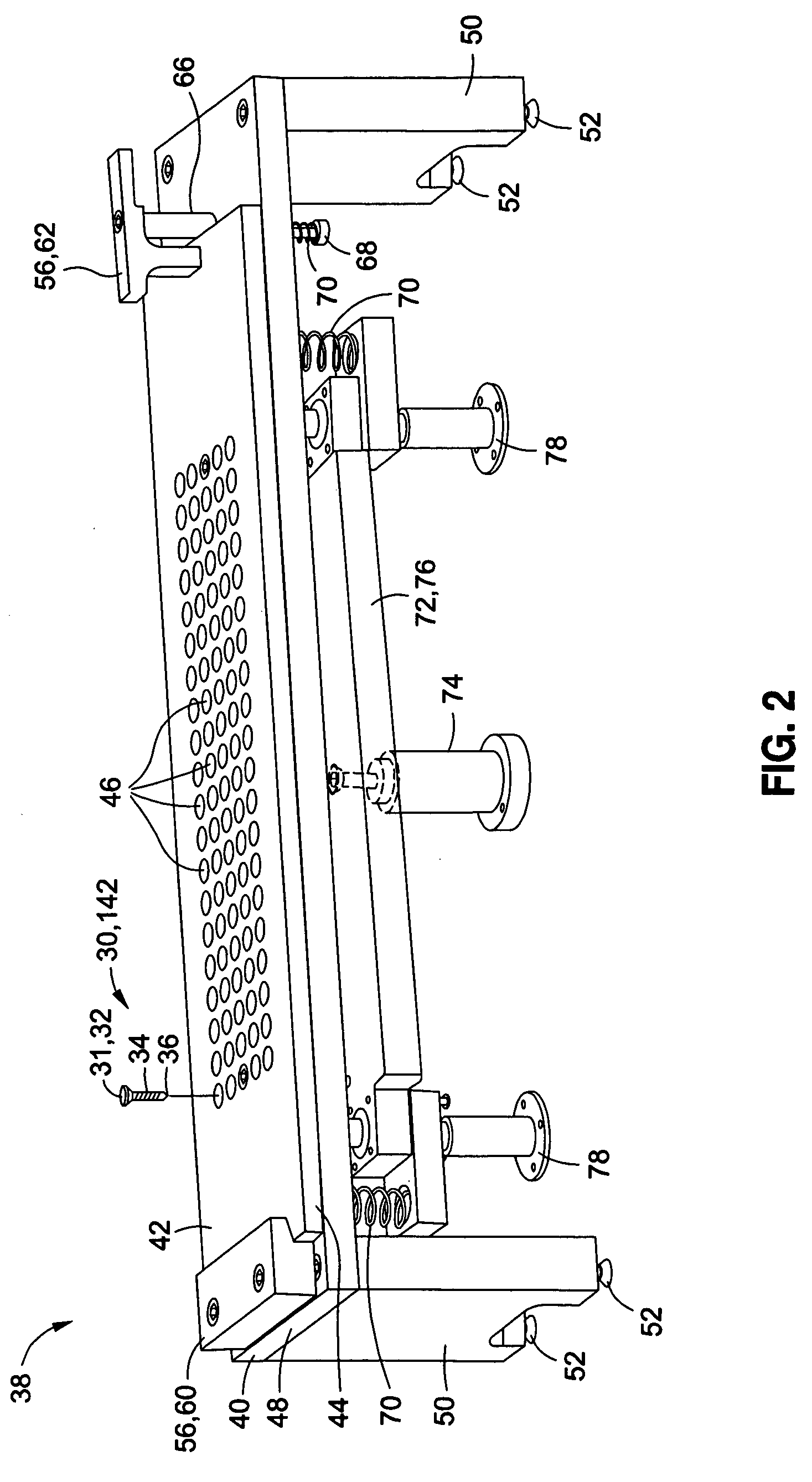
[0038]Referring now to the drawings wherein the showings are for purposes of illustrating preferred and various embodiments of the disclosure only and not for purposes of limiting the same, FIGS. 1-11B illustrate a self-contained painting apparatus 10 as may be used for applying a coating material 106 to one or more member surfaces 31 of one or more members 30. The members 30 may be provided in any size, shape or configuration without limitation. For example, the members 30 may be provided as elongate members 30 such as fasteners having fastener heads 32 which may comprise the member surface 31 to which the coating material 106 may be applied. The painting apparatus 10 is adapted to apply the coating material 106 to one or more of the member surfaces 31 of the members 30 in a controlled environment and in an automated manner as illustrated in FIGS. 12A-12B. The painting apparatus 10 may also be operative to apply various types of coating materials 106 such as paint to the member sur...


PUM

PropertyMeasurementUnit
Temperatureaaaaaaaaaa
Fractionaaaaaaaaaa

Abstract

A painting apparatus for applying a coating material to a member surface of a member comprises a housing, at least one slide rail, a rack assembly, a cross beam and a spraying device. The slide rail may be mountable within the housing and may have a plurality of rack positions. The rack assembly is mountable within the housing at one of the rack positions. The rack assembly is configured to support the member such that the member surface is exposed. The cross beam may be coupled to the slide rail. The cross beam is movable along the slide rail and is positionable at the rack positions. The spraying device is mountable on the cross beam and is configured to move along the cross beam while spraying the coating material onto the member surface.

Description

CROSS-REFERENCE TO RELATED APPLICATIONS[0001](Not Applicable)STATEMENT RE: FEDERALLY SPONSORED RESEARCH / DEVELOPMENT[0002](Not Applicable)FIELD[0003]The present disclosure relates generally to coating systems and, more particularly, to controlled-environment painting apparatuses for applying coatings to a plurality of items such as mechanical fasteners.BACKGROUND[0004]Manufacturers are continuously implementing new production techniques and build philosophies in efforts to reduce production cycle time and cost. Particularly for manufacturers of large-scale assemblies such as commercial aircraft, minor improvements to the production process can lead to appreciable reductions in production time and cost. One approach to reducing production cycle time and cost is to reduce the amount of labor required at final assembly. In this approach, instead of receiving a multitude of individual components and partially-completed subassemblies from a variety of different subcontractors for final as...

Claims


Application Information

Patent Timeline
IPC IPC(8): B05D1/02B05C5/00
CPCB05B13/02B05B13/041B05B15/12Y10T29/49741Y10T29/49782Y10T29/49595Y10T29/26Y10S118/11B05B16/00
Inventor DAVIS, BRUCE R.STEPAN, MICHAEL M.
Owner THE BOEING CO
Why Eureka
Try Eureka