Direct-injection spark-ignition engine

a spark ignition and direct injection technology, applied in the direction of brake systems, process and machine control, instruments, etc., can solve the problems of deterioration of combustion state, deterioration of combustion stability, and critical management of fuel injection timing, so as to promote catalyst activation and enhance combustion efficiency

Active Publication Date: 2010-07-15
MAZDA MOTOR CORP
View PDF7 Cites 19 Cited by
  • Summary
  • Abstract
  • Description
  • Claims
  • Application Information

AI Technical Summary

Benefits of technology

[0017]In view of the above circumstances, it is an object of the present invention to provide a direct-injection spark-ignition engine capable of maximally holding an injected fuel spray around a spark plug to reliably stabilize a combustion state in a combustion mode for promoting catalyst activation during cold engine operation, while enhancing combustion efficiency in a homogenous combustion mode during normal engine operation.

Problems solved by technology

However, a large amount of ignition timing retard causes deterioration in combustion stability.
However, in the operation of injecting fuel from the fuel injector toward the spark plug at a high pressure, the management of an fuel injection timing becomes more critical.
Specifically, if the fuel injection timing deviates from an adequate point even slightly, a problem of deterioration in combustion state will occur.
Particularly, during cold engine operation, it is difficult to reliably keep the fuel injection timing constant, due to high fuel viscosity.
Further, if the fuel injector is arranged to inject fuel toward the spark plug as in the Patent Document 1, fuel cannot be injected toward a lower region of the combustion chamber in a homogenous combustion mode during normal (warmed-up) engine operation, to cause a problem of deterioration in combustion efficiency during the homogenous combustion mode.
The engine disclosed in the Patent Document 2 is not originally intended to provide measures for early catalyst activation during cold engine operation, and thereby cannot solve the problems in the Patent Document 1.
Similarly, the engine disclosed in the Patent Document 3 is not originally intended to provide measures for early catalyst activation during cold engine operation, and thereby cannot solve the problems in the Patent Document 1.

Method used


Image

  • Direct-injection spark-ignition engine
  • Direct-injection spark-ignition engine
  • Direct-injection spark-ignition engine

Examples


Embodiment Construction

[0034]With reference to the drawings, the present invention will now be specifically described based on an embodiment thereof.

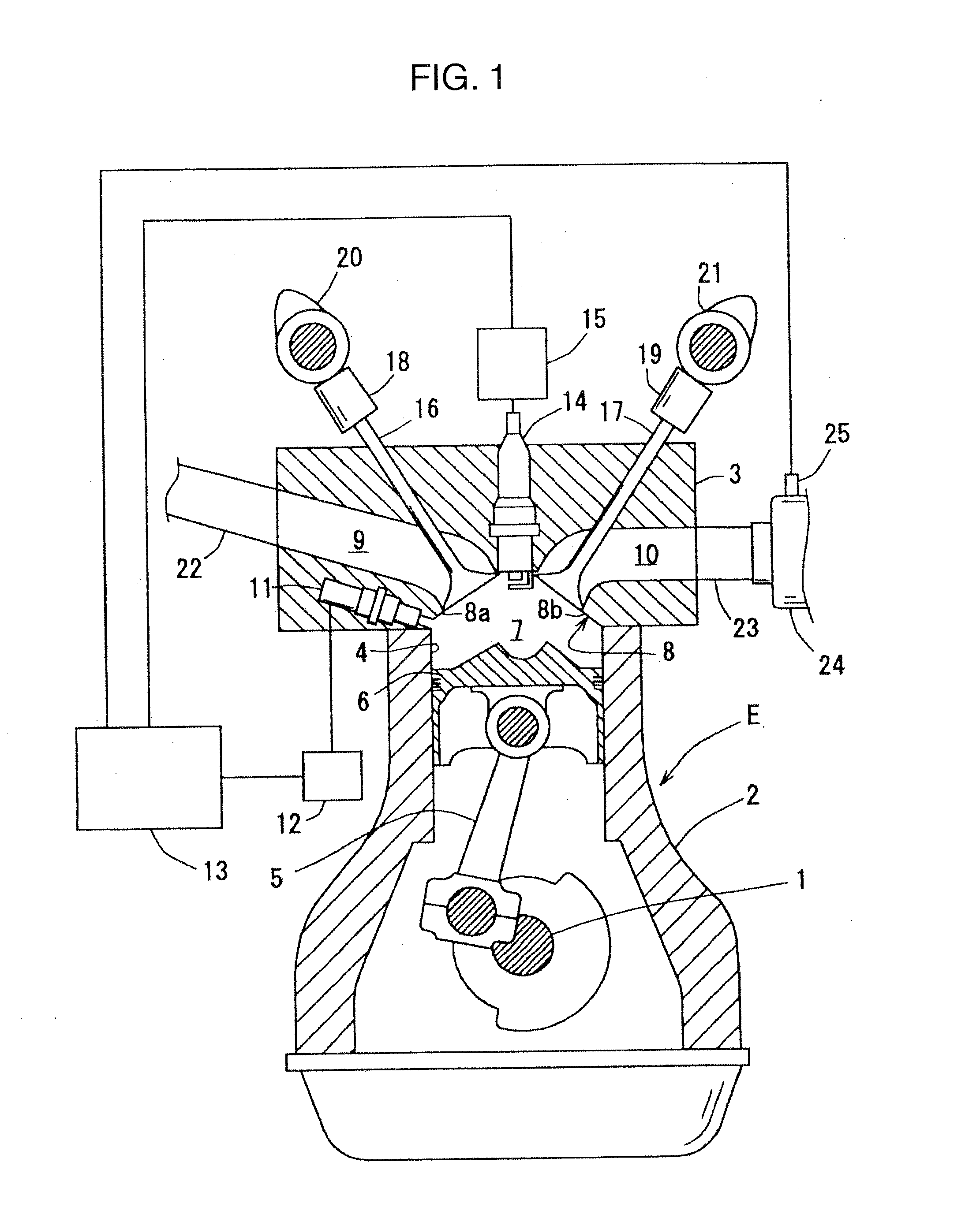
[0035]FIG. 1 is a schematic block diagram showing a direct-injection spark-ignition engine according to a first embodiment of the present invention. As shown in FIG. 1, this engine E is a four-cycle reciprocating spark-ignition engine, which integrally has a cylinder block 2 rotatably supporting a crankshaft 1, and a cylinder head 3 disposed above the cylinder block 2. The cylinder block 2 and the cylinder head 3 are formed to have a plurality of cylinders 4 thereinside.

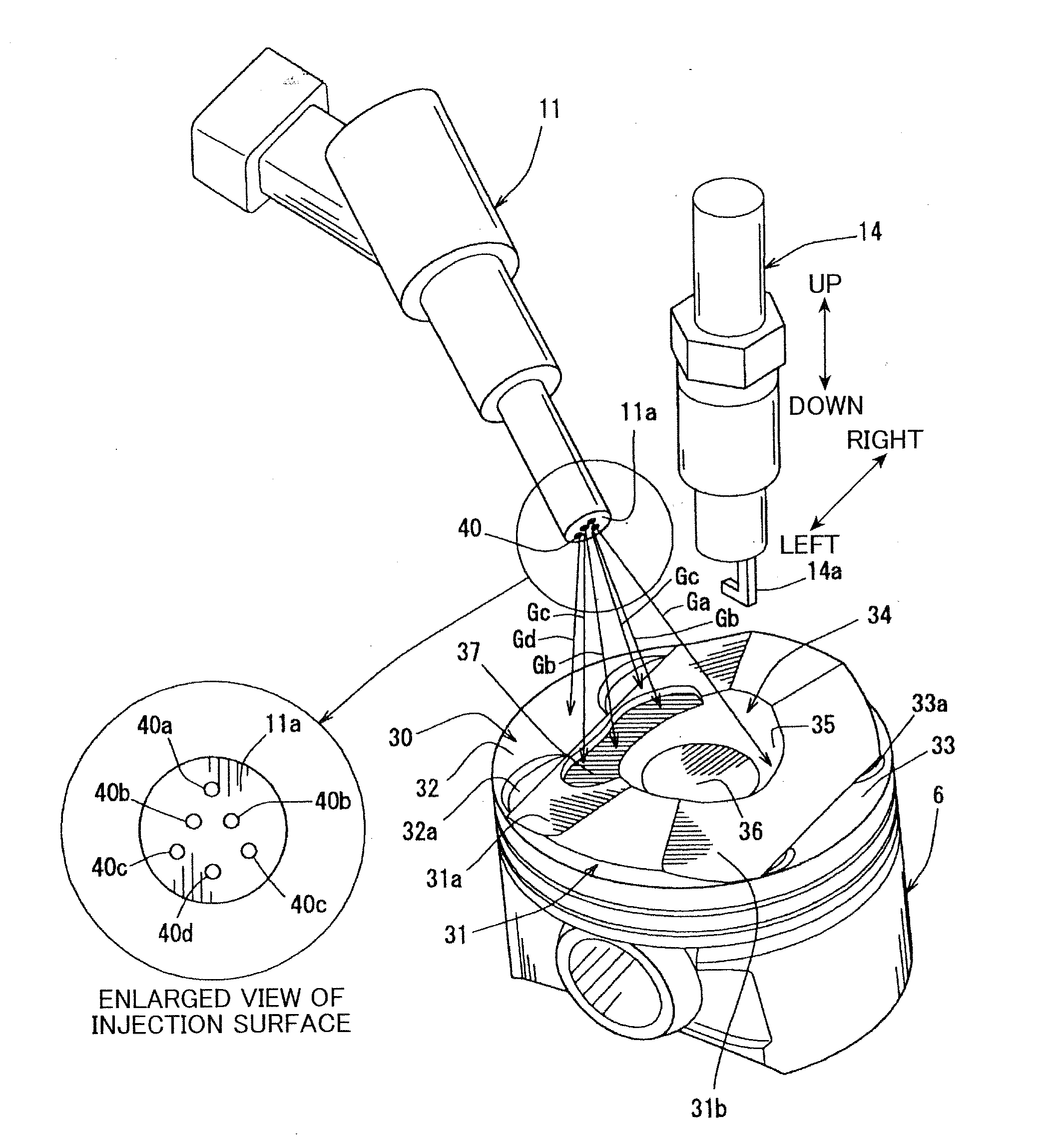
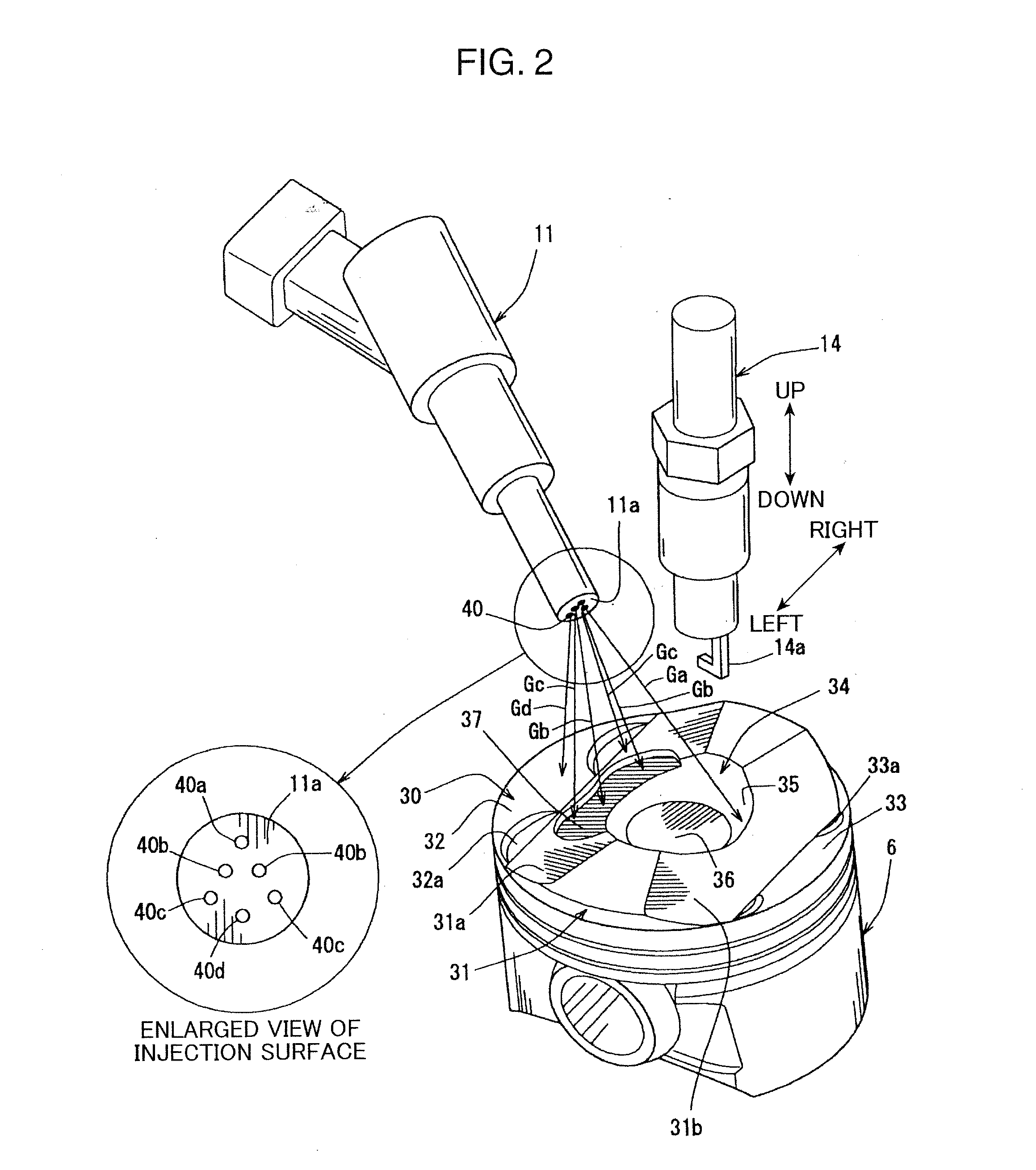
[0036]A piston 6 is fittingly inserted into each of the cylinders 4, while being connected to the crankshaft 1 through a connecting rod 5, so that a combustion chamber 7 is defined above the piston 6.

[0037]The cylinder head 3 has a lower surface partially formed as a roof wall surface 8 defining the combustion chamber 7 of each of the cylinders 4. The roof wall surface 8 is formed in a so-call...


PUM


Abstract

Disclosed is a direct-injection spark-ignition engine designed to promote catalyst activation during cold engine operation. A fuel injection timing for a fuel injection period in an compression stroke (second fuel injection period F2) is set to allow a first fuel spray Ga injected from a first spray hole 40a to enter a cavity 34 in a piston crown surface 30, and allow a second fuel spray Gb to impinge against a region of the piston crown surface 30 located closer to an injector than the cavity 34, so as to cause the second fuel spray Gb having a lowered penetration force due to the impingement to be pulled toward the cavity 34 by a negative pressure generated in the cavity 34 as a result of passing of the first fuel spray Ga therethrough. The direct-injection spark-ignition engine can maximally hold an injected fuel spray around a spark plug to reliably stabilize a combustion state in a combustion mode for promoting catalyst activation during cold engine operation, while enhancing combustion efficiency in a homogenous combustion mode during normal engine operation.

Description

BACKGROUND OF THE INVENTION[0001]1. Field of the Invention[0002]The present invention relates to a direct-injection spark-ignition engine, and more particularly to a direct-injection spark-ignition engine designed to promote catalyst activation during cold engine operation.[0003]2. Description of the Background Art[0004]Heretofore, with a view to achieving improvement in fuel economy, a direct-injection spark-ignition engine operable to directly inject fuel into each cylinder has been employed. In such a direct-injection spark-ignition engine, a compression ratio can be set at a relatively high value to enhance engine efficiency, and a fuel injection amount can be freely adjusted regardless of an intake air amount.[0005]Late years, in connection with tighter exhaust emission regulations, there has been an increasing need for achieving earlier catalyst activation. The earlier catalyst activation requires quickly raising an exhaust gas temperature. As means to raise an exhaust gas tem...

Claims


Application Information

Patent Timeline
Patent Type & Authority Applications(United States)
IPC IPC(8): F02B5/00F02M69/04
CPCF02B23/104Y02T10/125F02B2023/103Y02T10/12
Inventor NISHIMOTO, TOSHIAKIWATANABE, TOMOMINAKAYAMA, YOSHITERUFUJIKAWA, TATSUYAYAMAKAWA, MASAHISA
Owner MAZDA MOTOR CORP
Why Eureka
Try Eureka