
Drive apparatus for vehicle

a technology for driving apparatus and vehicle, which is applied in the direction of propulsion by batteries/cells, electric devices, gearing, etc., can solve the problems of reducing the size of the vehicle-installed components, the power conversion efficiency of the boost converter may be reduced by an increase, and the reactor becomes large in size, so as to ensure the capacity of cooling the reactor and avoid the increase in the effect of increasing the volume of the drive apparatus

Active Publication Date: 2010-07-15
TOYOTA JIDOSHA KK
View PDF7 Cites 42 Cited by
  • Summary
  • Abstract
  • Description
  • Claims
  • Application Information

AI Technical Summary

Benefits of technology

[0010]According to the drive apparatus for the vehicle described above, the reactor in the storage chamber can be immersed in the refrigerant supplied according to the rotation of the rotating electric machine. Therefore, without additionally providing a refrigerant (heat transfer medium) supplying mechanism, a configuration of cooling the reactor can be implemented. Furthermore, when compared with a configuration where the lubricant oil is just flown over the reactor, the capacity of cooling the reactor can be improved.
[0012]With such a configuration, the heat transfer medium in the storage chamber is provided with fluidity and, therefore, the cooling capacity can be improved.
[0014]With such a configuration, it becomes possible to ensure a wide opening through which the heat transfer medium is introduced and to sufficiently cool the portion that greatly generates heat, thereby ensuring the capacity of cooling the reactor.
[0016]Thus, using the lubricant oil of the rotating electric machine as the refrigerant, that is, instead of additionally using a refrigerant (such as cooling water, for example) for cooling the reactor core, an increase in the volume of the drive apparatus can be avoided and the capacity of cooling the reactor can be ensured. Furthermore, since an increase in the temperature of the heat transfer medium is suppressed by heat exchange with the case having great heat capacity, the capacity of cooling the reactor can be ensured.
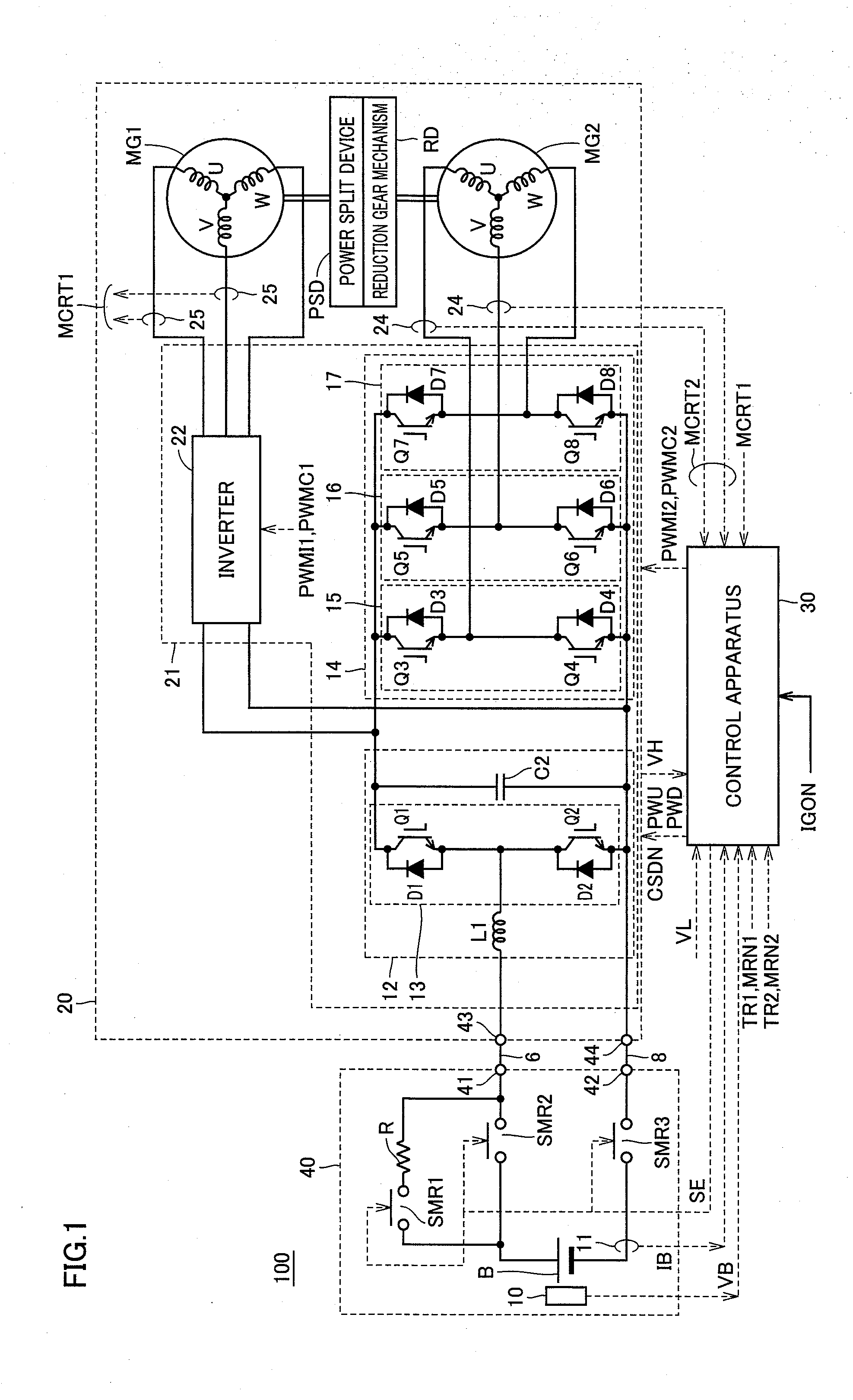
[0017]With the drive apparatus for the vehicle according to the present invention, in the structure in which the rotating electric machine and the group of electric circuitry (the converter, the inverter or the like) for driving the rotating electric machine are integrated, the performance of cooling the reactor can be ensured.

Problems solved by technology

It is concerned that the voltage converting efficiency of the boost converter may be reduced by an increase in the temperature of the reactor due to such heat generation.
Reduction of vehicle-installed components in size is a common problem to be solved for vehicles of every type.
Therefore, the reactor becomes great in size.
Accordingly, there is a problem in applying it to a boost converter as a component of a drive apparatus for a vehicle, of which adaptability to vehicle installation is weighed particularly heavily.
That is, Patent Document 3 is not aware of the problem of how to achieve both the efficient arrangement of a reactor and the ensured cooling performance, in such an integrated configuration.

Method used


Image

  • Drive apparatus for vehicle
  • Drive apparatus for vehicle
  • Drive apparatus for vehicle

Examples


case 102

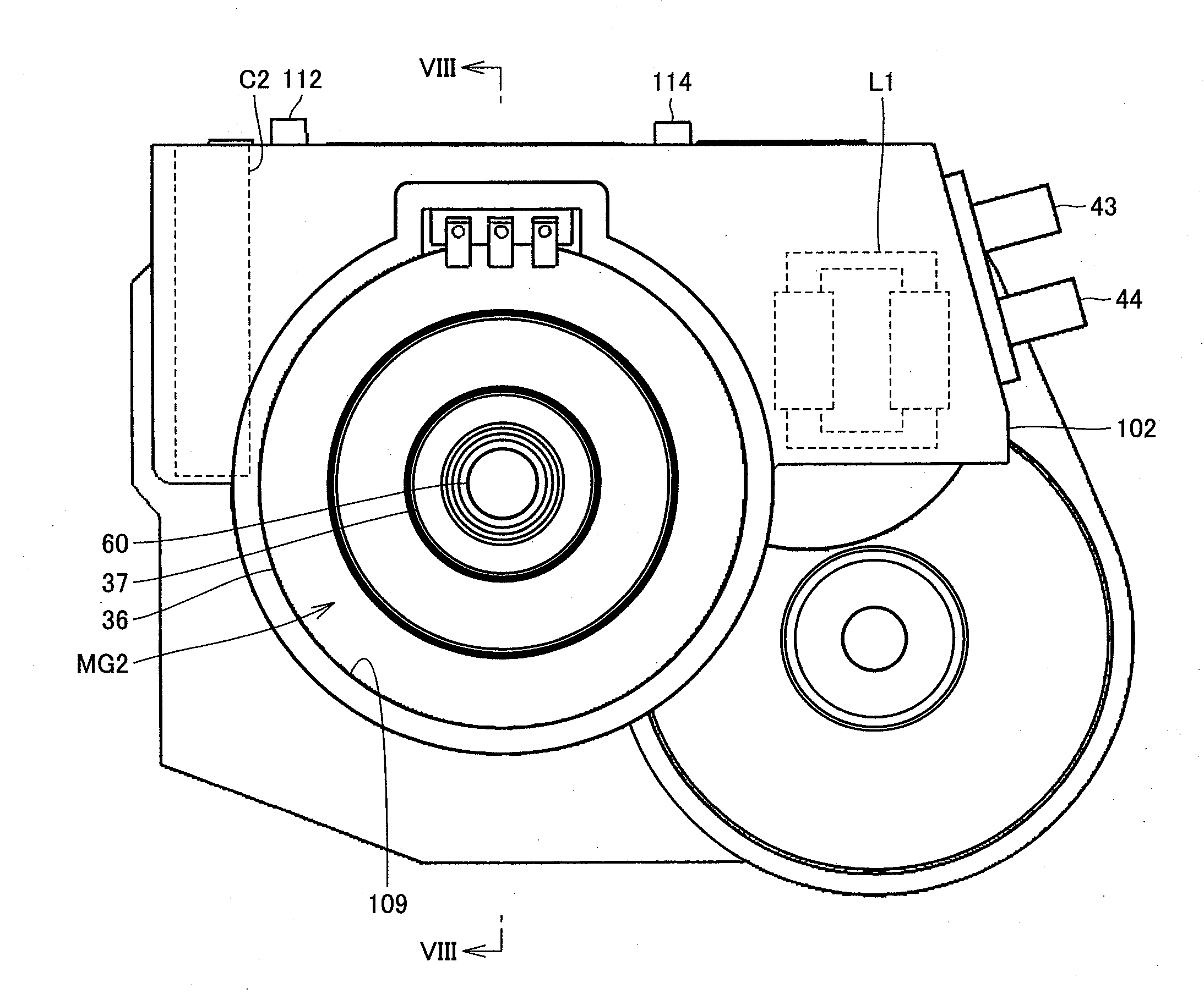
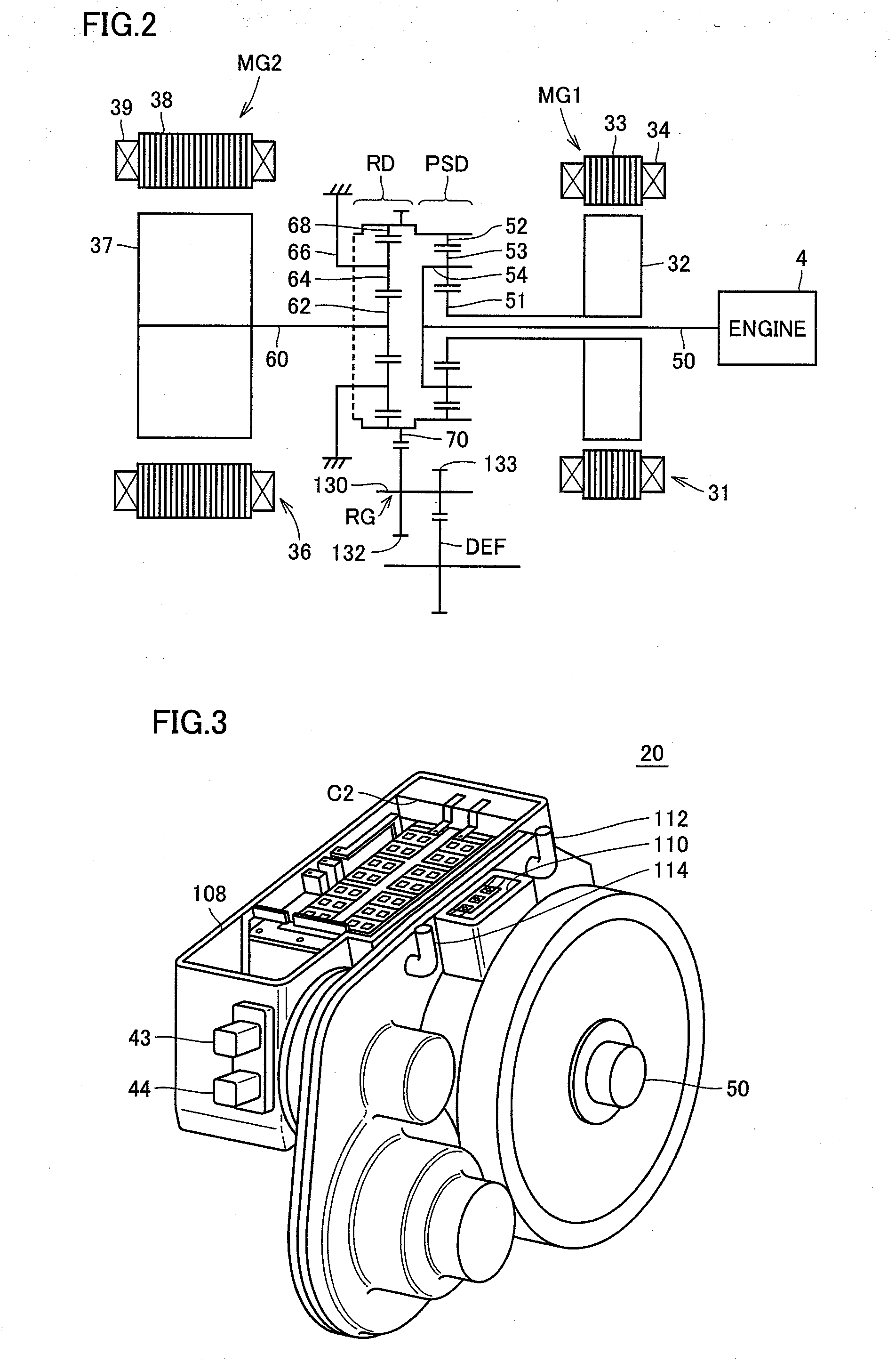
[0081]Case 102 is provided with an opening 108 for attaching the power control unit. Inside opening 108, capacitor C2 is stored in the left side portion (on the vehicle traveling direction side). A power element substrate 120 and terminal blocks 116, 118 are stored in the central portion. Reactor L1 is stored in the right side portion. Opening 108 is closed by a cover in a vehicle-installed state. The arrangement of capacitor C2 and reactor L1 may be switched so that capacitor C2 is arranged on the right side and reactor L1 is arranged on the left side.

[0082]That is, reactor L1 is arranged on one side of the rotation shafts of motor-generators MG1, MG2 and capacitor C2 is arranged on the other side of the rotation shafts. At a region between capacitor C2 and reactor L1, power element substrate 120 is arranged. Below power element substrate 120, motor-generator MG2 is arranged.

[0083]On power element substrate 120, inverter 22 controlling motor-generator MG1, inverter 14 controlling m...


PUM


Abstract

In a drive apparatus having an integrated structure where a rotating electric machine and an inverter and a voltage converter for driving the rotating electric machine are integrally stored in a case, lubricant oil carried up by the rotation of the motor-generator flows into a storage chamber for a reactor from an opening. The lubricant oil flown from the opening is stored inside the storage chamber with the use of a dividing wall provided between a portion where the motor-generator is stored and the storage chamber, whereby at least part of reactor is immersed in the lubricant oil. Thus, the performance of cooling the reactor is ensured.

Description

TECHNICAL FIELD[0001]The present invention relates to a drive apparatus for a vehicle. More specifically, the present invention relates to a drive apparatus for a vehicle, which includes a reactor as a component.BACKGROUND ART[0002]As one type of a drive apparatus for a vehicle, there is a known configuration of a drive apparatus for a hybrid vehicle having a motor as a motive power source for the vehicle, in which an output voltage of a battery is boosted by a boost converter and the boosted voltage is used for driving the motor. For example, Japanese Patent Laying-Open No. 2003-134606 (hereinafter referred to as Patent Document 1) discloses a drive apparatus for a hybrid vehicle having a boost converter including a reactor as a component.[0003]Generally, a reactor is configured by a core formed by a magnetic body and a coil wound around the core to ensure inductance. In such a configuration, the core generates heat in accordance with the electromagnetic energy conversion in the re...

Claims


Application Information

Patent Timeline
IPC IPC(8): B60K1/00
CPCB60K6/26B60K6/405B60K6/445B60K2001/003F16H57/0421Y02T10/6239H02K7/006H02K9/19H02K11/048H05K7/20927F16H2037/0866B60L3/003B60L15/007B60L15/2054B60L2210/14B60L2210/40B60L2220/14B60L2240/12B60L2240/36B60L2240/421B60L2240/423B60L2240/441B60L2240/443B60L2240/486B60L2240/547B60L2240/549B60L2270/20B60L50/61B60L50/16Y02T10/62Y02T10/64Y02T10/72Y02T10/7072Y02T10/70H02K11/33H02K5/20
Inventor YOSHIDA, TADAFUMI
Owner TOYOTA JIDOSHA KK
Learn More