
Pipe grip ring

a grip ring and pipe grip technology, applied in the direction of pipe joints, fluid pressure sealing joints, sleeves/socket joints, etc., can solve the problems of unsuitable 3′′ steel unsuitable 3′′ pipes of the same wall thickness, and inability to meet the requirements of 3′′ steel pipes,

Active Publication Date: 2010-07-15
KRAUSZ INDS DEVMENT
View PDF14 Cites 12 Cited by
  • Summary
  • Abstract
  • Description
  • Claims
  • Application Information

AI Technical Summary

Benefits of technology

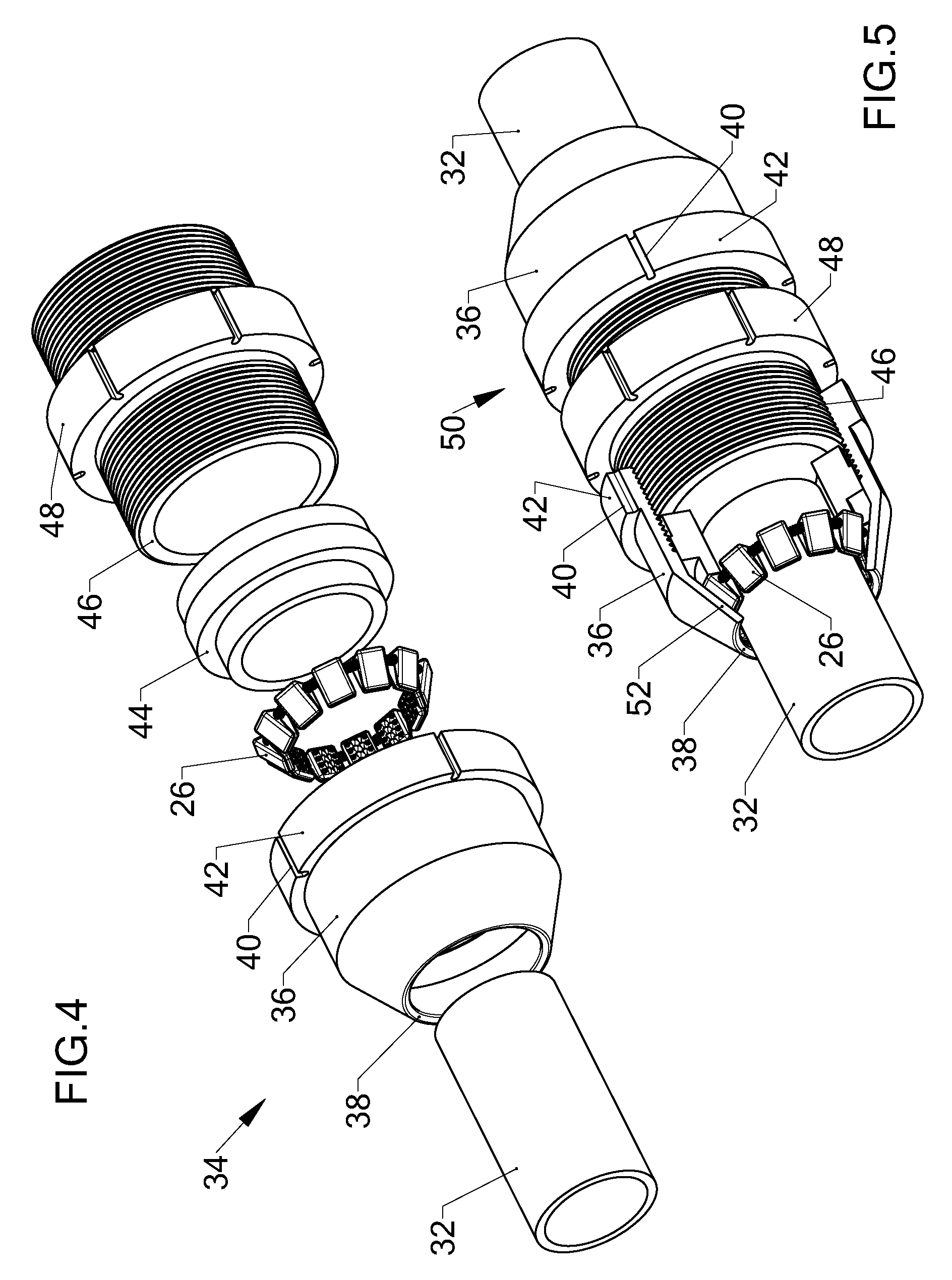
[0012]It is a further object of the present invention to provide a pipe fitting, particularly a pipe coupling having improved pull-out resistance, utilizing a plurality of the grip elements described in the present disclosure.
[0018]It will thus be realized that the novel grip element of the present invention can be used in contact with either metal or plastic pipes without requiring any adjustment. The array of larger teeth will penetrate the surface of a plastic pipe to a depth sufficient to prevent axial withdrawal. The smaller and thus stronger teeth will penetrate the surface of a metal pipe even if the larger teeth collapse.

Problems solved by technology

Thus a prior art pipe coupling for example suitable for a 3″ steel pipe will be unsuitable for a 3″ pipe of the same wall thickness when made of a plastic.
However there is some doubt regarding retention of steel pipes as the retainer member does not penetrate the outer skin of the pipe.
A similar disadvantage is present in the coupling disclosed by Hulsechos et al. in U.S. Pat. No. 6,481,755.
Some increase in holding power is provided by dents pressed into the grip ring, which is a complex and costly structure.
The risk is high that during installation the bolt will be wrongly adjusted.
This design requires machining and swaging one of the pipe ends, which is impractical in the field and even in the factory is difficult for long pipes.

Method used


Image

  • Pipe grip ring
  • Pipe grip ring
  • Pipe grip ring

Examples


Embodiment Construction

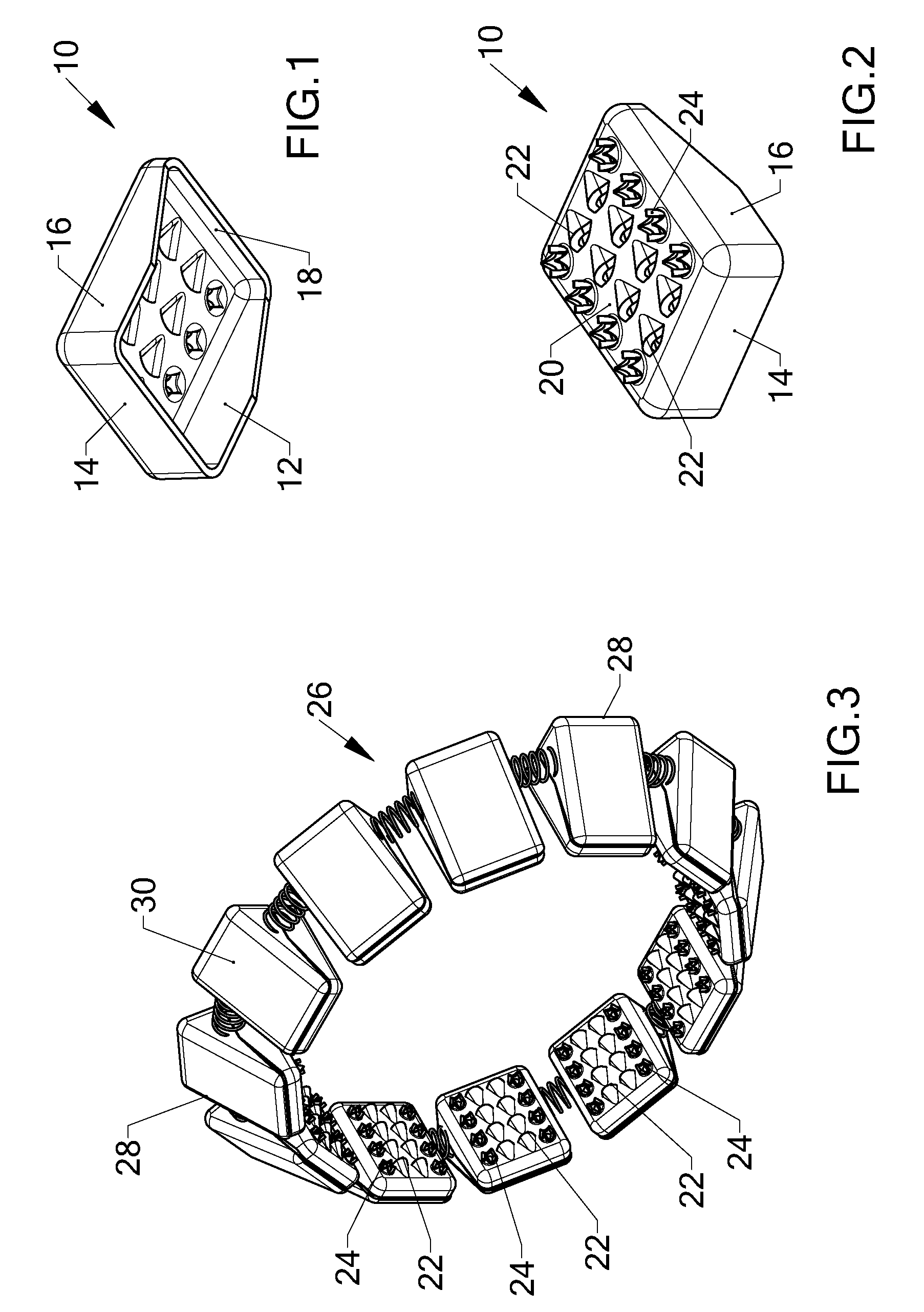
[0030]There is seen in FIGS. 1 and 2 a grip element 10 made of sheet steel. FIG. 1 shows the insides of the grip element where all walls 12, 141618 of the element are seen. In FIG. 2 the array of teeth of two different sizes is seen. The angled side walls 12, 16 convert the element 10 into a wedge-like structure. The exposed top outer surface 20 is a steel plate which is integral to all four walls.

[0031]The grip element 10 is provided with an array of large 22 and small 24 gripping teeth. The sharp edges of all teeth 22. 24 face the higher 14 of the two end walls, with the large teeth 22 projecting from the surface of the top outer surface 20 further than do the small teeth 24.

[0032]With reference to the rest of the figures, similar reference numerals have been used to identify similar parts.

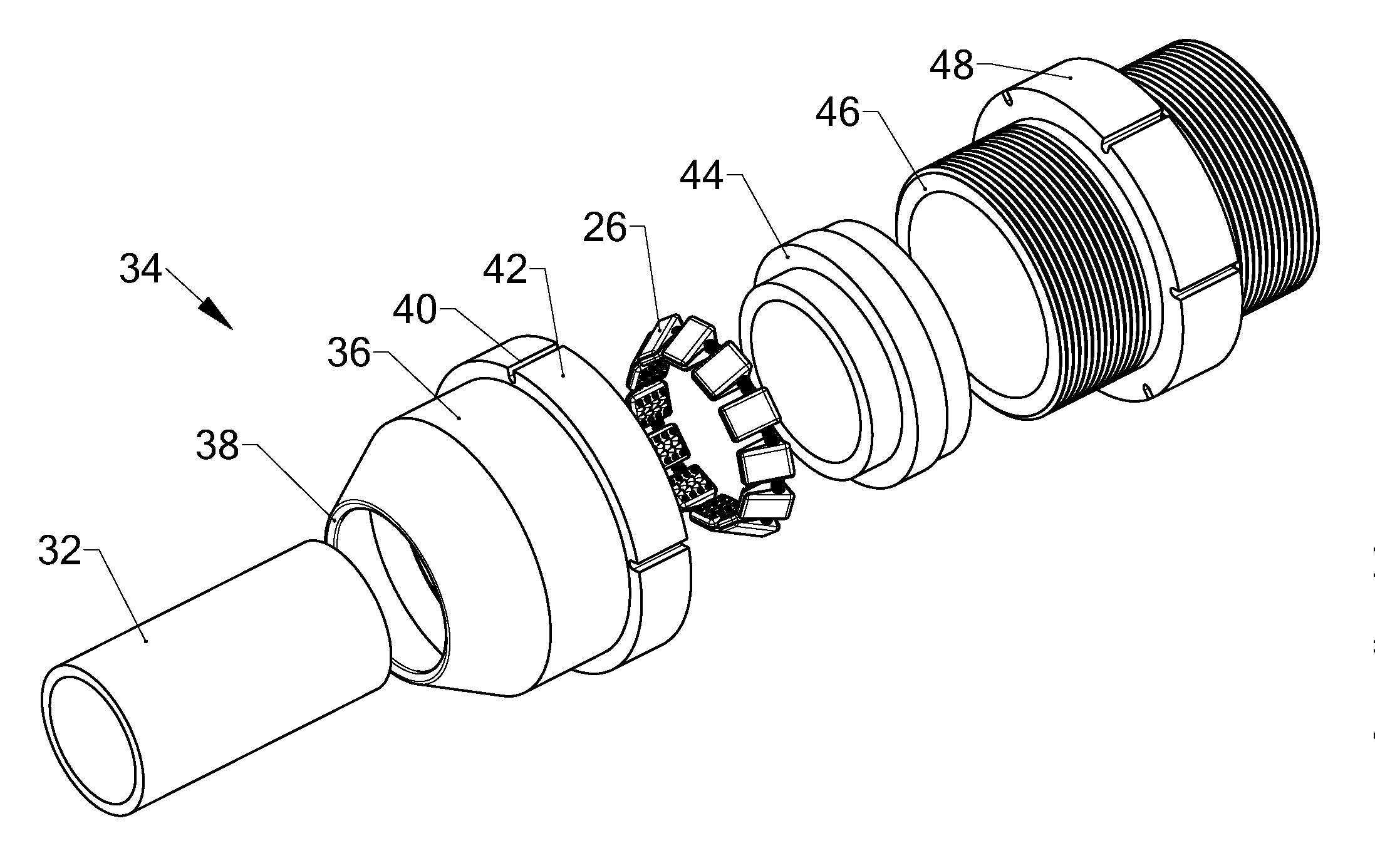
[0033]FIG. 3 illustrates a grip ring 26, for use in a pipe fitting to be described with reference to FIG. 4. The ring 26 retains several spaced-apart grip elements 28 which are radially evenly d...


PUM


Abstract

A grip element comprising a wedge-like structure supporting a metal plate, the exposed outer surface thereof being provided with an array of large and small gripping teeth. The large teeth project from the surface of said metal plate further than said small teeth. The invention further provides a grip element having a floor. The grip elements may be disposed around a ring for the purpose of pipe gripping. The ring is particularly useful in a pipe coupling to grip metal and plastic pipes

Description

FIELD OF INVENTION[0001]The present invention relates to a gripper element particularly useful for pipe line fittings. More particularly, the invention provides a grip element which can be used in pipe line fittings and couplings, for griping plastic or metal pipes, or any other material.BACKGROUND OF THE INVENTION[0002]While in the past all piping was made of metal, usually metal, today plastic piping is in widespread use and has been found suitable for many applications. Plastic pipes are widely used for the protection of electric cables, sewage, drainage and, where the pipe diameter is small for water under pressure. Larger sizes of plastic piping are suitable for conditions where there is little or no internal pressure, and in applications not exposed to solar radiation. The present invention relates particularly to intermediate size piping, typically the 50 to 200 mm range. Many prior art designs are suitable for pipes under about 5o mm, while the over 200 range is served well ...

Claims


Application Information

Patent Timeline
Patent Type & Authority Applications(United States)
IPC IPC(8): F16L21/02
CPCF16L19/061F16L19/083F16L19/065F16L21/06F16L37/084F16L37/0925F16L37/0927
Inventor KRAUSZ, ELIEZERCHIPROOT, AVI
Owner KRAUSZ INDS DEVMENT
Learn More