Receiving device including impedance control circuit and semiconductor device including impedance control circuit

a technology of impedance control circuit and receiving device, which is applied in the direction of electric generator control, line-transmission details, pulse techniques, etc., can solve the problems of affecting the operation of the receiving device, the ringing on the receiving side may not be restricted sufficiently, and the distortion of a waveform

Inactive Publication Date: 2010-07-15
DENSO CORP +1
View PDF9 Cites 23 Cited by
  • Summary
  • Abstract
  • Description
  • Claims
  • Application Information

AI Technical Summary

Benefits of technology

[0019]The present semiconductor device can restrict a flow of a surge current to the impedance control circuit. In addi

Problems solved by technology

Thereby, a ringing, that is, a distortion of a waveform such as an overshooting and an undershooting may occur.
Thus, even if an impedance is changed for a predetermined time as described in U.S. Pat. No. 6,326,803 or an output impedance is changed on a transmitting side as described in U.S. Pat. No. 6,487,250, a ringing on the receiving side may not be restricted sufficiently.
Thus, the ringing on the receiving side ma

Method used


Image

  • Receiving device including impedance control circuit and semiconductor device including impedance control circuit
  • Receiving device including impedance control circuit and semiconductor device including impedance control circuit
  • Receiving device including impedance control circuit and semiconductor device including impedance control circuit

Examples


first embodiment

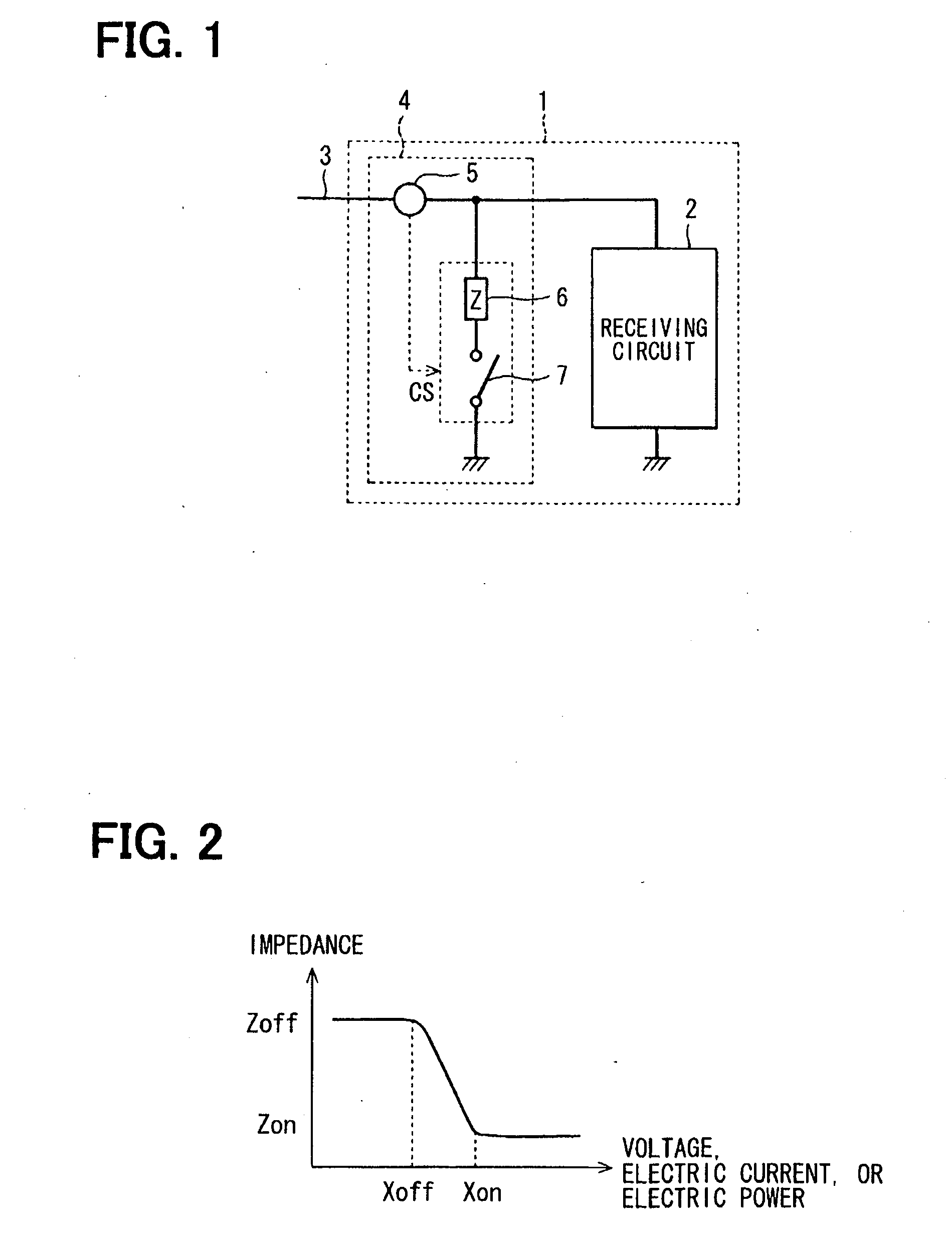
[0053]A receiving device 1 according to a first embodiment of the present invention will be described with reference to FIG. 1 and FIG. 2. The receiving device 1 includes a receiving circuit 2, a communication line 3, and an impedance control circuit 4 disposed between the communication line 3 and the receiving circuit 2. The impedance control circuit 4 includes a detecting part 5 inserted in the communication line 3, an impedance element 6 and a switch circuit 7 coupled between the communication line 3 and a ground. The detecting part 5, the impedance element 6, and the switch circuit 7 are coupled in series. The switch circuit 7 is normally open.

[0054]The detecting part 5 is configured to detect a physical value of a signal received through the communication line 3 and the physical value includes at least one of a voltage, an electric current, and an electric power. When the detected value is greater than a threshold value, the detecting part 5 outputs a control signal CS to the s...

second embodiment

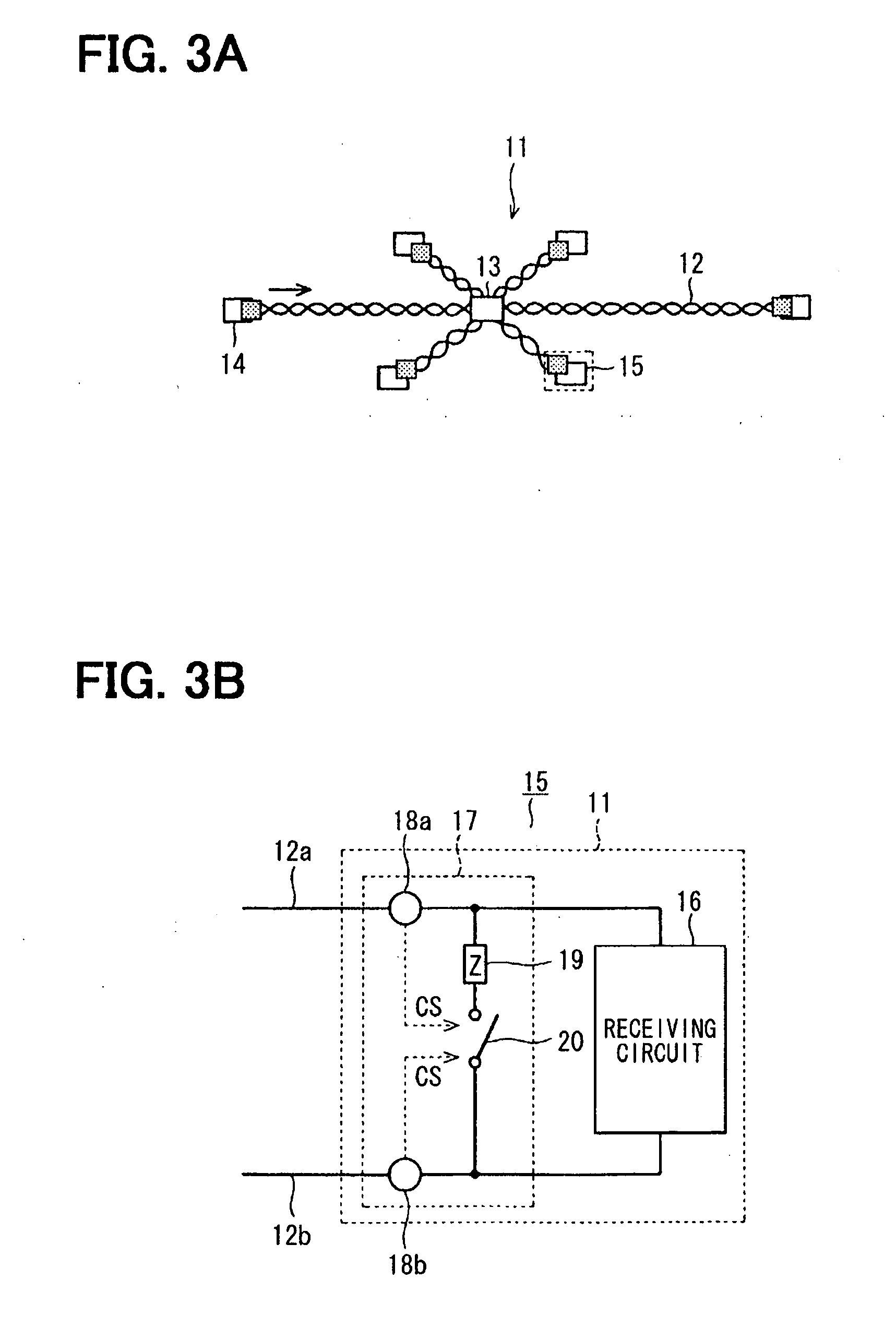
[0058]A receiving device 15 according to a second embodiment of the present invention will be described with reference to FIG. 3A and FIG. 3B. The receiving device 15 may be provided in a communication network 11 in which a differential signal is transmitted through a communication line 12. The communication line 12 is formed of a pair of phase conductors, that is, a bus line plus (BP) and a bus line minus (BM). For example, a signal line 12a is the phase conductor BP and the signal line 12b is the phase conductor BM. In the communication network 11, a plurality of communication nodes are coupled with each other through the communication line 12. In the communication line 12, a hub 13 is inserted.

[0059]The receiving device 15 is one of the communication nodes. The receiving device 15 is configured to receive a differential signal from a transmitting device 14 through the communication line 12. The receiving device 15 includes a receiving circuit 16 and an impedance control circuit 1...

third embodiment

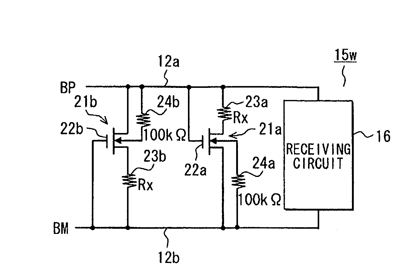
[0062]A receiving device 15 according to a third embodiment of the present invention will be described with reference to FIG. 4A-FIG. 5B. The receiving device 15 can be provided in a communication network 11. In the communication network 11 illustrated in FIG. 4A, a length of the communication line 12 between the transmitting device 14 and the hub 13 is about 4 m and a length of the communication line 12 between the hub 13 and the receiving device 15 is about 2 m. The transmitting device 14 is a trunk node having a matching circuit. The receiving device 15 is a branch node without a matching circuit. The communication network 11 can be used for FlexRay (registered trademark) that is an example of in-vehicle local area network (in-vehicle LAN).

[0063]Between the pair of signal lines 12a and 12b, an impedance control circuit 21a, an impedance control circuit 21b, and a receiving circuit 16 are coupled in parallel. The impedance control circuit 21a includes an N channel metal-oxide-semi...


PUM


Abstract

A receiving device includes a receiving circuit and an impedance control circuit. The receiving circuit receives a signal transmitted through a communication line. The impedance control circuit is coupled with the receiving circuit and has a detecting part. The detecting part detects a physical value of the signal and the physical value includes at least one of a voltage, an electric current, and an electric power. The impedance control circuit changes an input impedance based on the detected value so that a ringing of the signal is reduced.

Description

CROSS REFERENCE TO RELATED APPLICATIONS[0001]The present application is based on and claims priority to Japanese Patent Applications No. 2008-67710 filed on Mar. 17, 2008 and No. 2008-96464 filed on Apr. 2, 2008, the contents of which are incorporated in their entirety herein by reference.BACKGROUND OF THE INVENTION[0002]1. Field of the Invention[0003]The present invention relates to a receiving device including an impedance control circuit and a semiconductor device including an impedance control circuit.[0004]2. Description of the Related Art[0005]In a case where a digital signal is transmitted through a communication line, a part of a signal energy may reflect on a receiving side at a time when signal level changes. Thereby, a ringing, that is, a distortion of a waveform such as an overshooting and an undershooting may occur. Various technologies are suggested for restricting a ringing. For example, U.S. Pat. No. 6,326,803 (corresponding to JP-A-2001-127805) discloses a terminati...

Claims


Application Information

Patent Timeline
IPC IPC(8): H04B3/02H02H9/04
CPCH01L27/092H01L27/0928H01L27/1203H04L25/0292H04L25/0272H04L25/0278H04B3/30
Inventor SUZUKI, YOUICHIROUMAEDA, NOBORUNAKANO, TAKASHINAGASE, KAZUYOSHIKONDO, KOJITAKAHASHI, SHIGEKIOZEKI, YOSHIHIKO
Owner DENSO CORP
Why Eureka
Try Eureka