Separator of solid particles from steam-gas mixture

a technology of solid particles and vacuum gas, which is applied in the direction of liquid separation agents, combination devices, and dispersed particle filtration, etc., can solve the problems of hindering the purposeful work of the dust chamber, and equipment failure, so as to reduce the hydraulic resistance of the whole ash treatment facility, the effect of increasing the productivity not reducing the cleaning efficiency of the vapour-gas mixtur

Active Publication Date: 2010-07-22
EESTI ENERGIA OLITOOSTUS
View PDF34 Cites 13 Cited by
  • Summary
  • Abstract
  • Description
  • Claims
  • Application Information

AI Technical Summary

Benefits of technology

[0020]to increase the productivity of vapour-gas mixture without decreasing the efficiency of cleaning of vapour-gas mixture, the second stage...

Problems solved by technology

This structure has several shortcomings that decrease the cleaning efficiency and cause equipment failures.
This in turn hinders the purposeful work of the dust chamber, i.e. the gravitational settling of semi-coke decreases, because the speed of vapour-gas mixture going through main body accelerates so that semi-coke particles are carried through by vapour-gas mixture, i.e. the removal speed of semi-coke particles is higher than the gravitational settling speed of particles.
This contravenes with the objective of refractory lining and insulation, because the material used for refractory lining loses its thermal insulation properties.
Since this location is most subjected to semi-coke removal, it will cause breakdown of lamella compensators and following leakage.
This in turn causes the stoppage of cyclone-operations for repairs.
This deficiency is al...

Method used


Image

  • Separator of solid particles from steam-gas mixture
  • Separator of solid particles from steam-gas mixture
  • Separator of solid particles from steam-gas mixture

Examples


Embodiment Construction

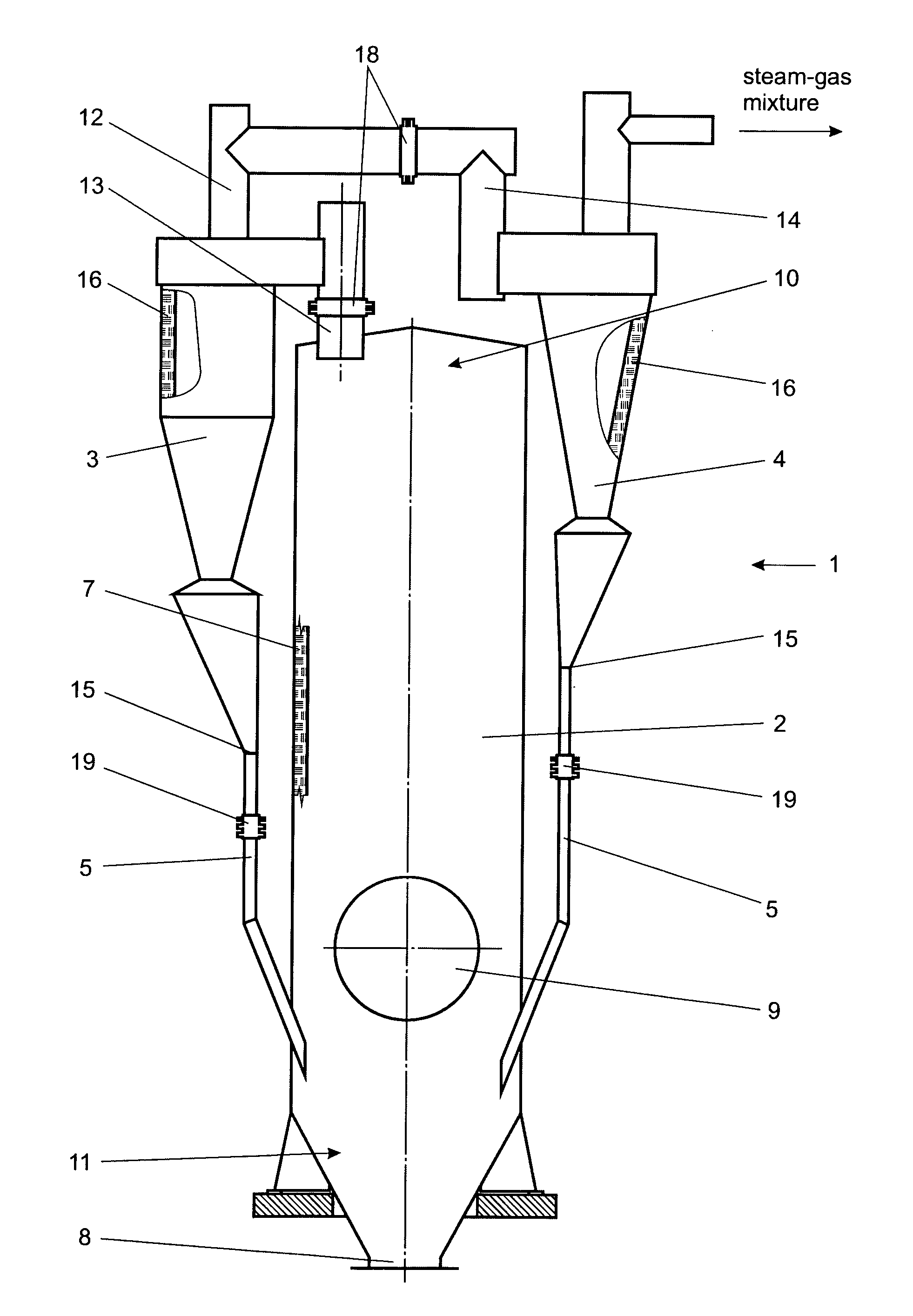
[0025]A device in which the pyrolysis of pulverized fossil fuel (e.g. oil shale) or material containing organic matter using solid heat-carrier process takes place, includes the separator (dust chamber) for separating solid particles from vapour-gas mixture. The temperature of vapour-gas mixture entering into treatment junction is about 480° C. and it contains particles of semi-coke up to 230 g / m3, the rest is hydrocarbon vapours, water vapour and pyrolysis gas and other admixtures and gases.

[0026]Vapour-gas mixture is purified in this device by the gravitational settling of particles.

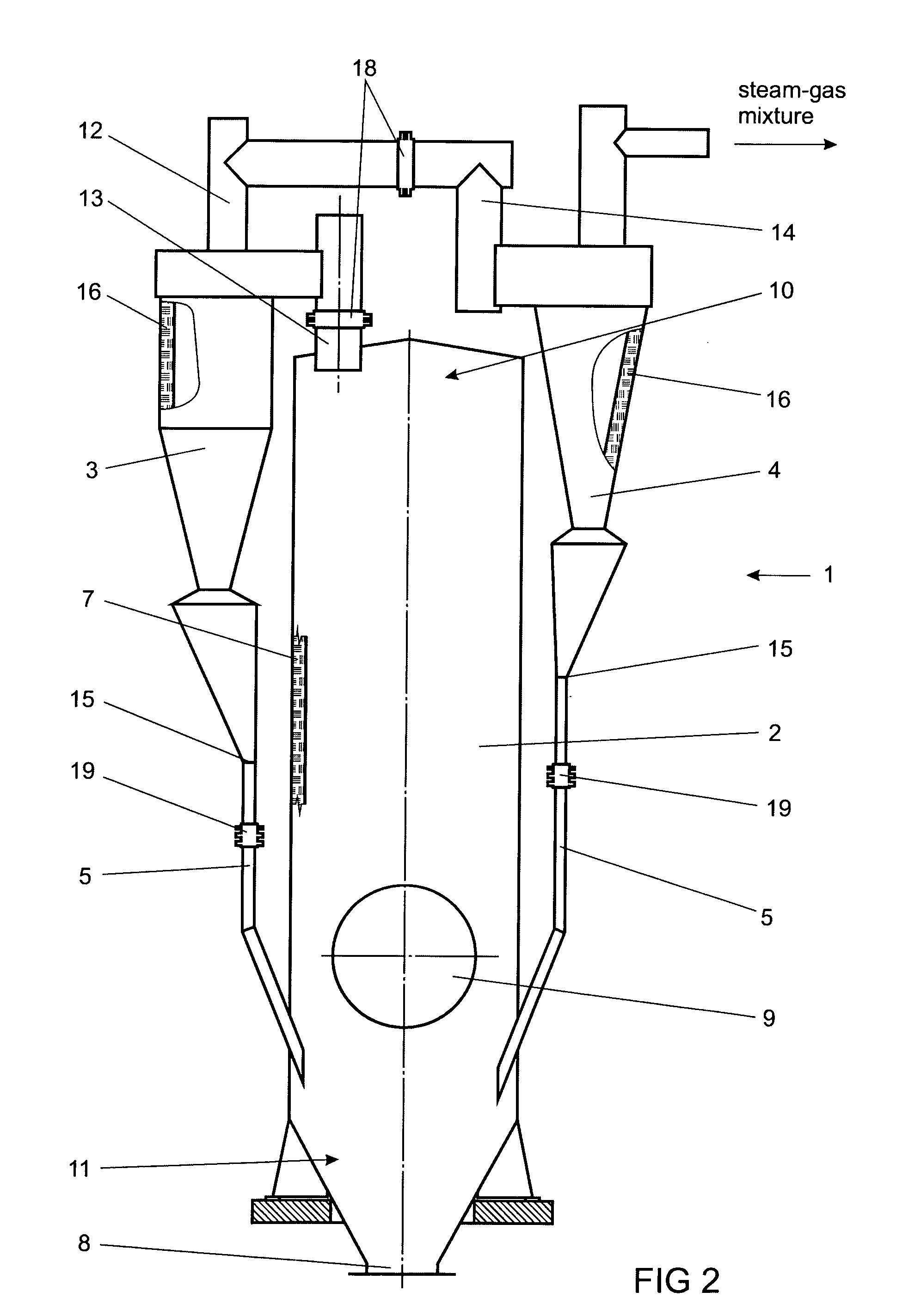
[0027]The separator for separating solid particles from vapour-gas mixture or dust chamber 1 according to the present invention illustrated in the FIG. 2 comprises the main body 2, which internal surface is covered with internal refractory lining 7. Internal refractory lining 7 is made from wear-proof and non-porous material like concrete, so that vapour-gas mixture cannot leak through and the hydrocar...


PUM

PropertyMeasurementUnit
Diameteraaaaaaaaaa
Electrical resistanceaaaaaaaaaa
Heightaaaaaaaaaa

Abstract

The present invention is related to the separator (dust chamber) for separating solid particles from vapour-gas mixture, particularly to the structure of the dust chamber belonging amongst installation of the plant processing the fossil fuels or materials containing organic matter. The dust chamber (1) for separating solid particles from vapour-gas mixture comprises main body (2) with inner refractory lining (7) arranged to the inner surface of said main body, first and second stage cyclones (3, 4), lamella compensators (18, 19), dust removal conduits (5, 15) and inlet conduit (13) of the vapour-gas mixture into the first cyclone (3). The main body (2) of the dust chamber (1) is manufactured in all height from the cylinder of equal diameter and first and second stage cyclones (3, 4) are placed outside of the main body (2) of the dust chamber (1). For the refractory lining of the main body (2) of the dust chamber (1) and first and second stage cyclones (3, 4) the non-porous and wear proof material, for example concrete, is used.

Description

TECHNICAL FIELD[0001]The present invention is related to the separator (dust chamber) for separating solid particles from vapour-gas mixture, particularly to the structure of the dust chamber belonging amongst installation of the plant processing the materials containing the fossil fuels or organic substances.BACKGROUND ART[0002]As regards to state of the art, the separator (dust chamber) for separating solid particles from vapour-gas mixture known and used by patent applicant is described as follows with reference to FIG. 1. In order to get a clearer and better view of the device known from state of the art, and also to draw out differences with this invention, details of the separator that correspond to those known from the state of the art are marked with the same position numbers, adding an apostrophe (') to position number in order to differentiate between the two.[0003]The separator (dust chamber) for separating solid particles from vapour-gas mixture known from state of the a...

Claims


Application Information

Patent Timeline
IPC IPC(8): B04C5/26B01J8/00B01J19/02
CPCB01J8/0055
Inventor KAIDALOV, ALEKSANDRKINDORKIN, BORISS
Owner EESTI ENERGIA OLITOOSTUS
Why Eureka
Try Eureka