REFERENCE NUMERALS IN DRAWINGS
[0016]10 Pedal-driven part
[0017]11 Gear plate
[0018]12 Crank
[0019]13 Pedal
[0020]20 Motor-driven part
[0021]21 Electric motor
[0022]22 Drive-gear
[0023]23 Relay-gear
[0024]30 Gearing mechanism
[0025]31 Transmission gear disc
[0026]32 First transmission member
[0027]33 Second transmission member
[0028]50 Frame
[0029]51 Rear wheel
DETAILED DESCRIPTION OF THE INVENTION
(1) The Preferred Embodiments
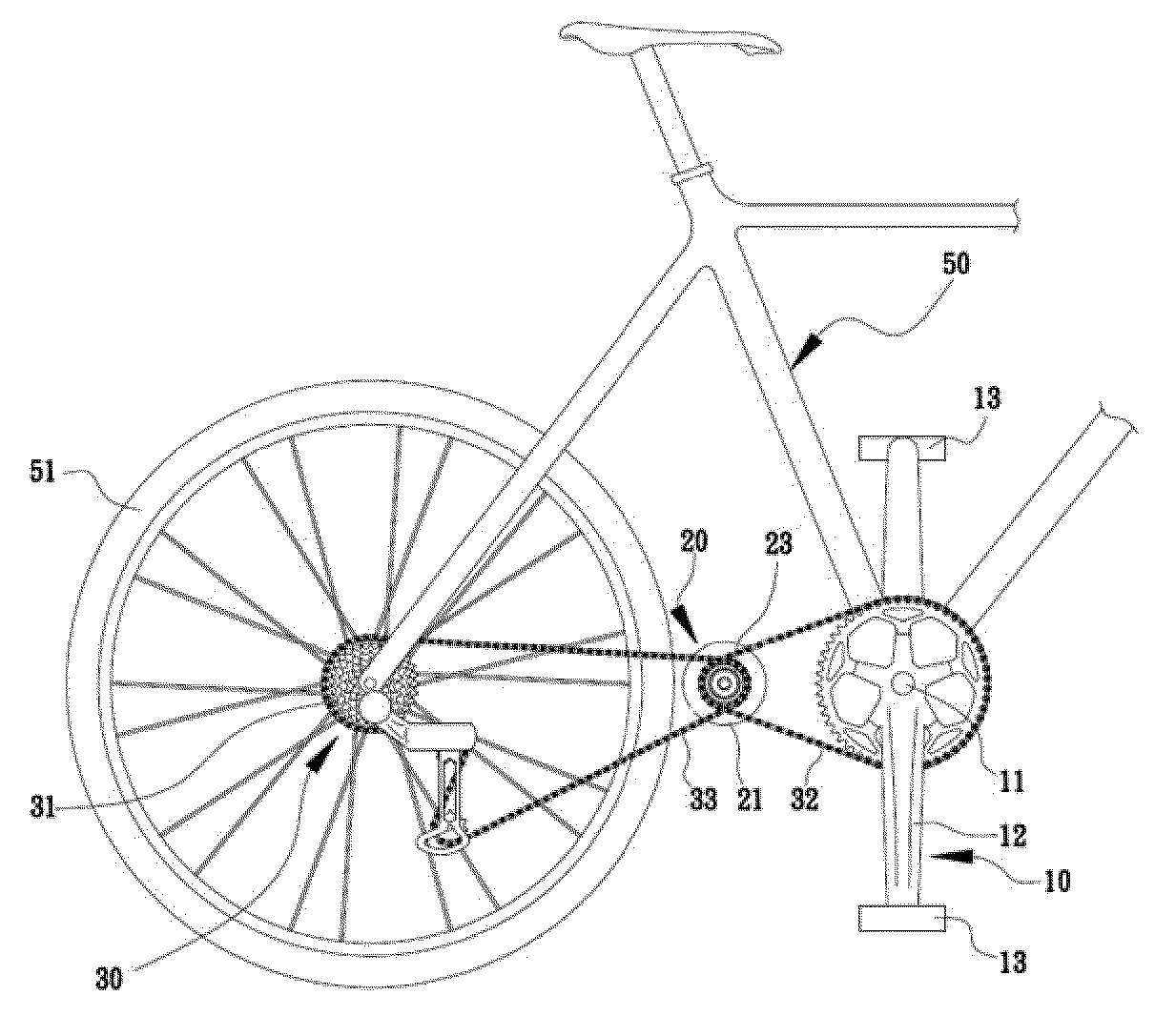
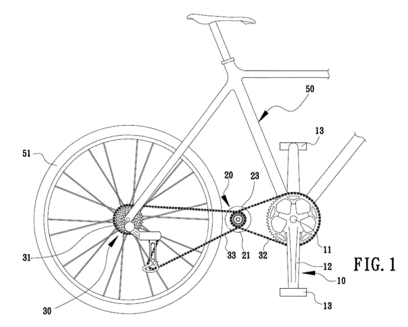
[0030]The present invention provides a dual-drivetrain for powering a vehicle by pedaling with an assistance of an attached motor (FIG. 1). It comprises a pedal-driven part 10, a motor-driven part 20, power conveying means, and a controller.
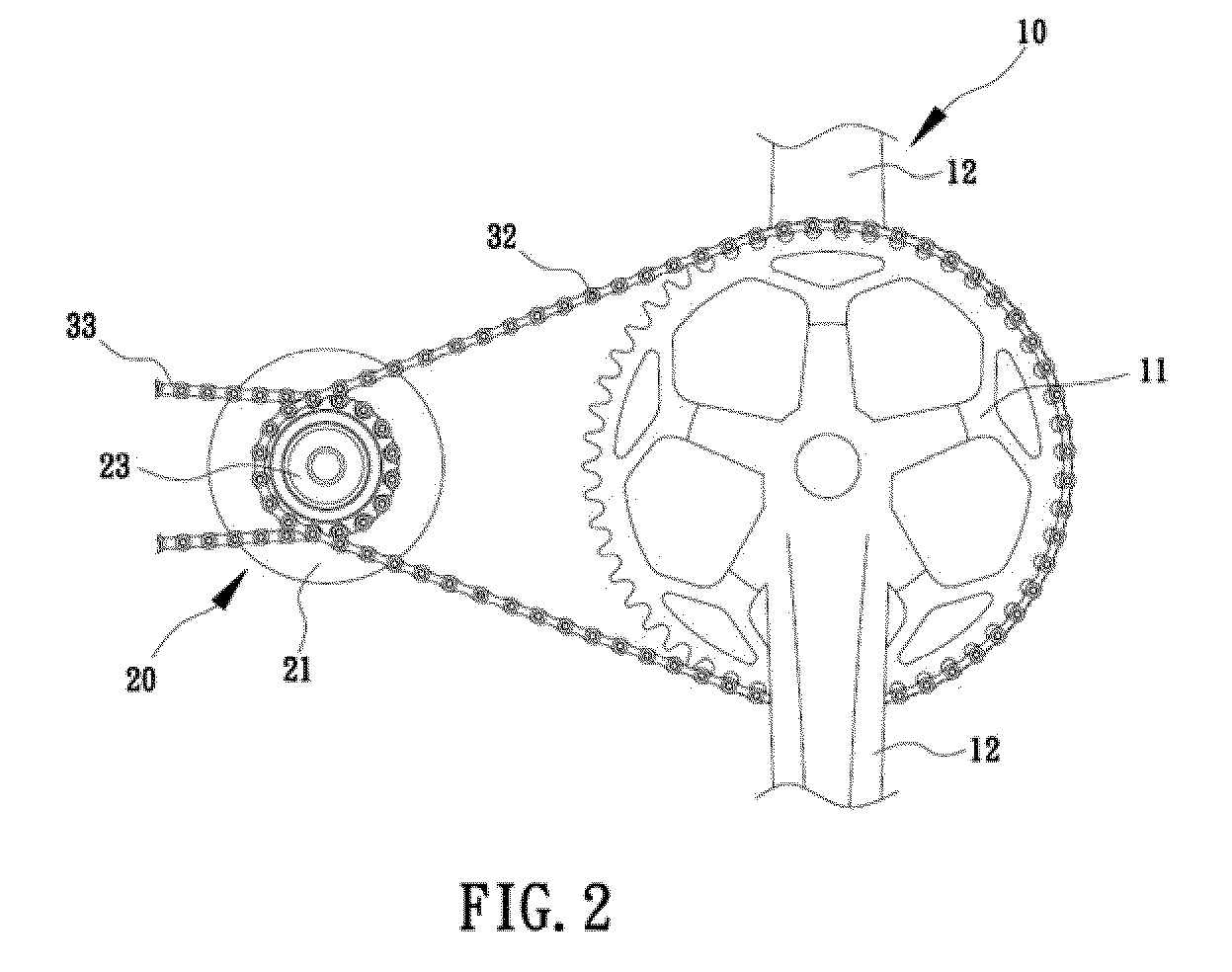
[0031]Pedal-driven part 10, also known as a crankset in a traditional bicycle, is pivotally mounted to a frame 50 of the vehicle (FIG. 1). With reference to FIGS. 2 & 5, it has at least one gear plate 11 (also called chainwheels or front gears), a pair of cranks 12 normally mounted 180 degree out of phase to gear plate 11, and a pair of pedals 13 pivotally attached to each crank 12.
[0032]Motor-driven part 20 is also firmly attached to frame 50, situated preferably between pedal-driven part 10 and a real wheel 51 (FIGS. 1 & 2). As illustrated in FIG. 3, motor-driven part 20 has an electric motor 21, a drive-gear 22, and a relay-gear 23. Both drive gear 22 and relay gear 23 are pivotally attached to the armature of electric motor 21. While drive-gear 22 can rotate either clockwise or counterclockwise, relay-gear 23 rotates only clockwise. These have been disclosed previously by Inventor (Taiwan New Model Patent Notice No. 397023) and will not be addressed in detail here. While drive-gear 22 mechanically couples real wheel 51, relay-gear 23 couples pedal-driven part 10. See supra.
[0033]The power conveying part comprises a first transmission member 32 and a gearing mechanism 30 (FIGS. 4 & 5). First transmission member 32 can be as simple as a roller chain (FIGS. 2 & 3) that couples gear plate 11 and relay-gear 23, resulting in a synchronized rotation of relay-gear 23 with pedal-driven part 10.
[0034]Gearing mechanism 30 is a variable-ratio transmission system for selecting appropriate gear ratios for optimum efficiency or comfort while riding a bike. It can be a derailleur mechanism or an internal hub gear mechanism. As illustrated in FIGS. 4 & 5, the preferred gearing mechanism of the present invention is the derailleur mechanism that includes second transmission member 33, a transmission gear disc 31, and a rear derailleur (reference numeral not shown). Transmission gear disc 31 is a set of multiple rear-gears that has various diameters (FIGS. 4 & 5) and concentrically attaches to real wheel 51 (FIG. 1). Second transmission member 33 can be simply a roller chain that rotationally couples one of rear-gears (i.e., transmission gear disc 31), the rear derailleur and relay-gear 22 (i.e., motor-driven part 20) (FIGS. 4 & 5). The rear derailleur mechanism is a well-known gearing mechanism of the art of bicycle; thereby it will not addressed here in detail.
[0035]The controller (not shown in Figures) can be is mounted on the any predetermined position of frame 50 (e.g., on the down tube of the frame, on the handlebars or at the ends of triathlon bars). It includes a regulator and a shifter. See infra.
[0036]The shifter is used for remotely operating gearing mechanism 30 by various well-known methods. For example, many modern bicycles utilize a cable, (e.g. a Bowden cable) for mechanically lining the shifter to the rear-derailleur (chain-guide) of the gearing mechanism. When a rider operates the lever of the shifter while pedaling, the change in cable tension moves the chain-guide from side to side, “derailing” the chain (i.e, second transmission member 23) onto different gears of Transmission gear disc 31.
[0037]The regulator, which electrically couples a battery (no shown in Figures) and electric motor 21, is used for remotely regulating the rotational speed of electric motor 21. Depending of the type of electric motor 21, various devices are known to control motor's speed. For example, generally, the speed of a DC motor is proportional to the voltage applied to it, and the torque is proportional to the current. Speed control can be achieved by variable sbattery tappings, variable supply voltage, resistors, or electronic controls. Pulse-width modulation (PWM) is the preffered method for controlling the speed of electric motor 21, and TL494 is the preferred electronic chip, which provides PWM power-control circuit.
[0038]The regulator preferably further comprises a sensor that provides a feedback loop for adjusting rotor's speed based on vehicle's speed. It electrically couples a vehicle's speed monitor and provides feedback signal to the regulator for adjusting motor's speed based on vehicle's speed. This kind of feedback loop electronic device is well-known to one skilled in the art.
(2) The Best Mode of Carrying Out the Invention
[0039]While pedalling, relay-gear 23 is synchronized with gear plate 11; the synchronization is detected by a monitor mounted in a predetermined position of frame 50. The monitor sends signals to the sensor, which is electronically couples to the regulator that regulates electric motor 21. Electric motor 21 rotates relay-gear 23 and produces torque output, so that raider can save labor/energy of pedalling.
[0040]Not only pedalling activates electric motor 21, but also it regulates and adjusts the speed of electric motor 21 via feedback signals from the sensor to the regulator. While the pre-determined speed of vehicle is reaching, the feedback signal stops electric motor 21 from running; relay-sprocking 23 becomes gear idling, almost without resistance. Accordingly, the armature of electric motor 21 is not rotating, is protected from wearing out, thus elongate the lifetime of electric motor 21. While the speed is not reaching, the feedback signal protentiates electric motor 21 to run and kick in extra speed. Moreover, the controller further includes the shifter. Operating the shifter, riders can cruise all terrains by their choice of gears (i.e., speed vs. torque ration).
[0041]Referring to FIGS. 3 &5, besides pedaling, riders can directly use the controller to activate electric motor 21 for running drive-gear 22, and use second transmission member 33 to rotate transmission gear disc 31 for driving wheel 51. Here, gear plate 11 does not rotate by pedaling, relay-gear 23 keeps idle, and thus wheel 51 is powered by electric motor 21 (i.e., electro drive mode). In the electro drive mode, riders can also operate the shifter to “derail” to various gears and enjoy multiple gear-speed effect.
[0042]Additionally, when electric motor 21 is shut down, riders will use pedals directly to lead relay-gear 23 and drive-gear 22 to operate, and then through second transmission member 33 to run transmission gear disc 31, whereby wheel 51 is rotated with pedaling (i.e., pedal drive mode). Still, in the pedal drive mode, riders can operate the shifter to “derail” to various gears and enjoy multiple gear-speed effect.
[0043]While pedaling, the sensor signals feed back to regulator; that in turn regulates electric motor 21 and rotates drive-gear 22, whereby a huge torque output is produced. The torque enables drive-gear 22 and relay-gear 23 to produce the synchronous operation; whereby wheel 51 is powered by both pedaling and electric motor 21 (i.e., dual mixed mode). Still, in the dual mixed mode, riders can operate the shifter to “derail” to various gears, enjoy multiple gear-speed effect and enhance uphill climbing ability.
[0044]It is worth mentioning that when relay-gear 23 is operated by Gear plate 11, drive-gear 22 is running with relay-gear 23. Only at this moment, electric motor 21 keeps the status without function (i.e., the armature of electric motor 21 dose not rotated with drive-gear 22), so that it can reach the effects of protecting electric motor 21. Thus, motor-driven part 20 has been disclosed by thee original inventor (Taiwan New Model Patent Notice No. 397023 where its second wheel chain is equivalent to the drive-gear 22 of FIG. 3, and where its one-way rotation component is equivalent to relay-gear 23.
[0045]Finally, please refer to FIG. 6 that is a schematic diagram of the state of transmission of this invention. The present invention approaches the electric and pedal output of duel driven effects mainly through the motion of electric motor 21 and gear plate 11: namely, when drive-gear 22 operates, the settings of relay-gear 23 can produce gear idling, almost without resistance; the gear idling protects electric motor 21 and extends the service life of electric motor 21. Because transmission gear disc 31 is formed by a plurality of rear-gears of various diameters, regardless pedal-driven or electric-driven, riders can operate on the shifter of the controller for controlling gearing mechanism 30 so that second transmission member 33 will couple drive-gear 22 to one of the rear-gears accordingly, whereby suitable speed-torque ratio can be achieved. The riders can enjoy multiple gearing (speed-to-torque ratio) while riding in various kinds of terrains and exercising by their own choice (pedal-, electronic-, or mixed-mode).
[0046]Moreover, pedal-driven part 10 may include a plurality of gear plate 11 of various diameters. This design is known and used in the modern bicycles, so that it will not describe here further. However, it is worth to mention here that the functional wheel transmission gear disk 11 is formed by the designed gear plate 11 of plural concentric outer diameters, to form a set of various stall transformation with relay-gear 23, to enable the rider to proceed the stall transformation of gear plate 11, further to correspond to the stall transformation of transmission gear disc 31, in order to reach the effects of multi-stage speed change; Also, the controller (not shown in figure) can be the output signal, to be the speed adjustment of electric motor 21, to achieve the effects of variable-speed change and stop. The preferred embodiments and the best mode of carrying out the invention are intended to illustrate but not to limit the present invention. It will be apparent to one skilled in the art that various substitutions and modifications may be made to the invention disclosed herein without departing form the scope and the spirit of the invention. Accordingly, these substitutions, and modifications, and their legal equivalents are intended to be within the scope of present invention.