Spectrally Controlled Illuminator and Method of Use Thereof

Inactive Publication Date: 2010-07-22
OPTIMUM TECH
View PDF14 Cites 9 Cited by
  • Summary
  • Abstract
  • Description
  • Claims
  • Application Information

AI Technical Summary

Benefits of technology

[0006]Light from the source is directed through one or more optical filters. The optical transmission of each filter has been designed such that the combined effect of the filters is to produce an illumination beam that has a pre-determined optical spectrum, said spectrum calculated to be better matched to the illumination task at hand than the inherent spectrum of the source. The set of filters in th

Problems solved by technology

The spectrum of the source is known a priori and typicall

Method used


Image

  • Spectrally Controlled Illuminator and Method of Use Thereof
  • Spectrally Controlled Illuminator and Method of Use Thereof
  • Spectrally Controlled Illuminator and Method of Use Thereof

Examples


Embodiment Construction

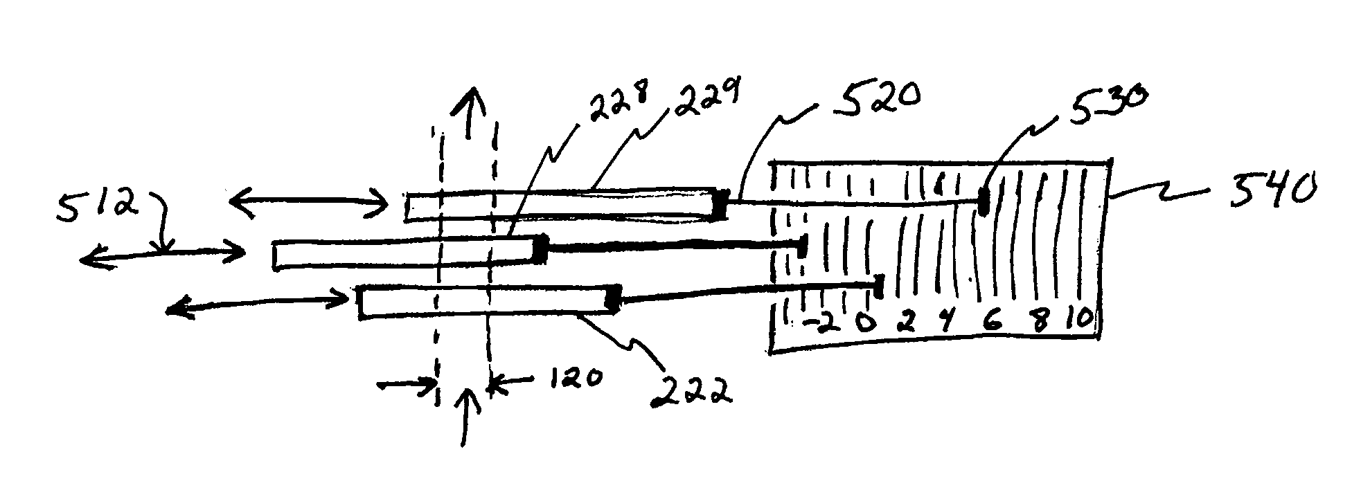
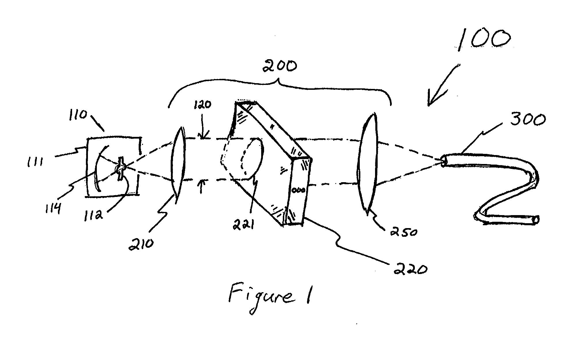
[0042]Referring to FIG. 1, an embodiment of the invention is an optical illuminator 100, which is typically used in optical experiments or in the measurement of the optical properties of a test object. Illuminator 100 comprises a source 110 of light and a bank 220 of optical filters. Filter bank 220 modifies the wavelength spectrum of source 110. Typically illuminator 100 also comprises beam forming optical elements 210 and 250 that match the beam parameters required inside filter bank 220 to the source 110 and to an output port, typically an optical fiber 300. For example, in the figure, element 210 is illustrated as converting an expanding cone of light into a generally collimated beam with beam size 120. The beam forming elements 210, 250 and the filter bank 220 form an optical spectrum equalizer 200.

[0043]Source 110 is selected to match the wavelength, power, temporal response and other specifications of the measurement or test instrument in which the illuminator is to be used. ...


PUM


Abstract

An optical spectrum equalizer and method, for modifying the output of a source of optical radiation. One or more optical filters are arranged in series in the path of the source. At least one filter defines a spatially-varying filter function. The position of at least one filter relative to the source is adjusted so that the filters together, as a whole, equalize the source spectrum by reducing the relative power of the source output at one or more of its wavelengths.

Description

FIELD OF THE INVENTION[0001]This invention generally relates to the field of optical illuminators, particularly to wide-band optical illuminators that use light sources with non-uniform spectra, such as xenon or mercury arc sources.BACKGROUND OF THE INVENTION[0002]Many optical measurement or test apparatuses operate by illuminating a test object with light from a source of known properties and measuring / observing the response of the test object in terms of reflection, absorption, scattering, or other means. A common procedure for making a measurement with such an apparatus includes the measurement of source properties—often the optical power spectrum—to be used as a calibration. This calibration is particularly important for certain classes of sources, such as arc lamp sources, for which the optical power spectrum can vary with time, temperature, lamp age, operating voltage, and other parameters that affect the source's spectral output. For critical measurements, this type of calibr...

Claims


Application Information

Patent Timeline
IPC IPC(8): G02B5/22
CPCG01J1/24G01J3/02G01J3/0237G01J3/12G01J2003/1213G02B5/20G02B6/29362G02B6/29391G02B6/29395G02B6/4215
Inventor CHINNOCK, RANDAL B.
Owner OPTIMUM TECH
Why Eureka
Try Eureka