Laser diode driver with back terminator and optical transmitter providing the same

a laser diode driver and back terminator technology, applied in the direction of electromagnetic transmission, electromagnetic transceivers, semiconductor lasers, etc., can solve the problems of increasing the power consumption of the laser diode driver, and difficult to lower the power supply voltag

Active Publication Date: 2010-07-22
SUMITOMO ELECTRIC IND LTD
View PDF6 Cites 32 Cited by
  • Summary
  • Abstract
  • Description
  • Claims
  • Application Information

AI Technical Summary

Benefits of technology

[0009]The back terminator of the present invention may further provide another passive device directly connected between the output terminals ...

Problems solved by technology

However, such back termination circuits disclosed in the prior arts provides only a resistor connected between two outputs of the LD-Driver or between the output of the LD-Driver and the power supply.
Such configurations shunt the driving current to be provided...

Method used


Image

  • Laser diode driver with back terminator and optical transmitter providing the same
  • Laser diode driver with back terminator and optical transmitter providing the same
  • Laser diode driver with back terminator and optical transmitter providing the same

Examples


Embodiment Construction

[0019]Next, preferred embodiments according to the present invention will be described as referring to accompanying drawings. In the description of the drawings, the same elements will be referred by the same numerals or the symbols without overlapping explanations.

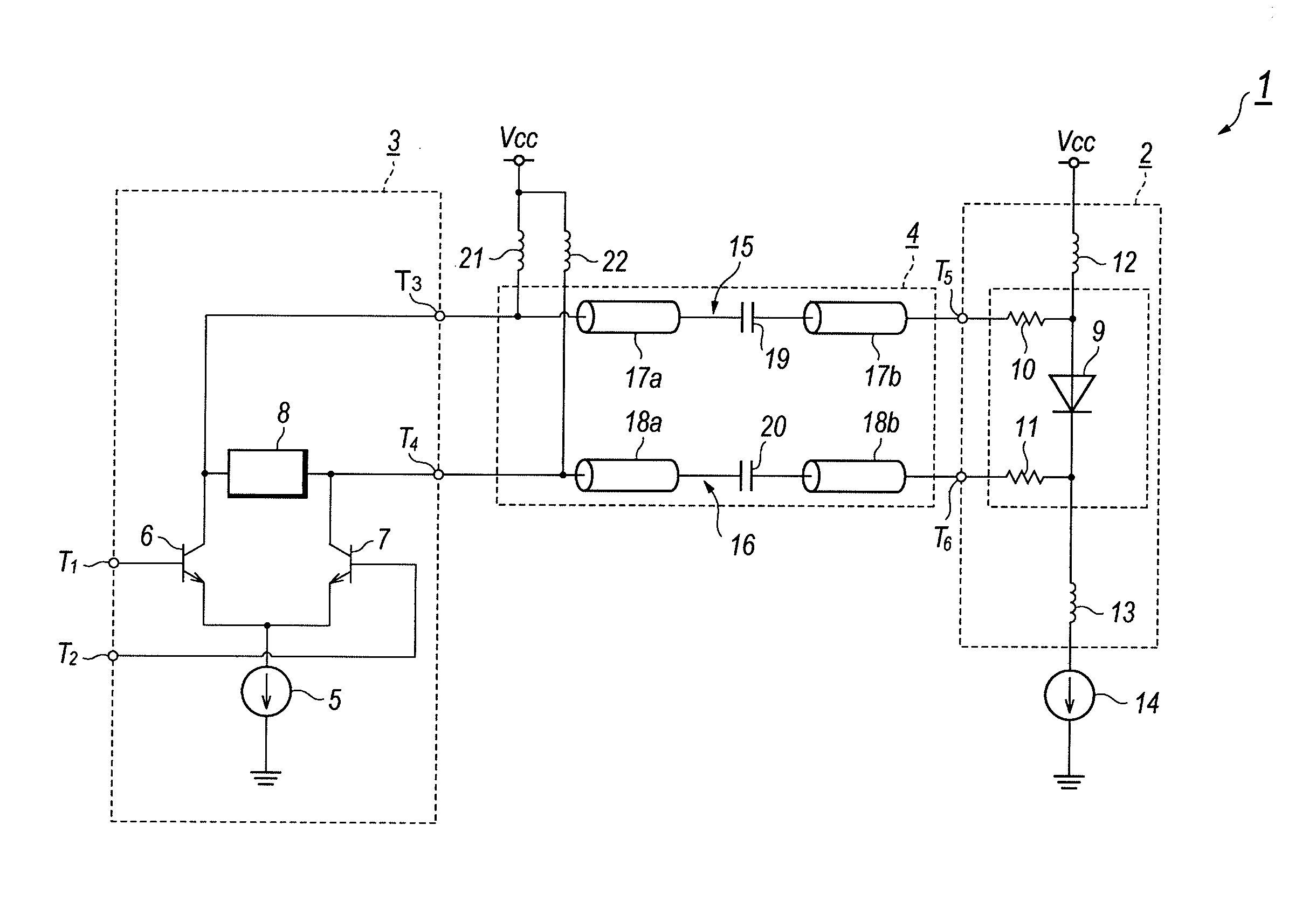
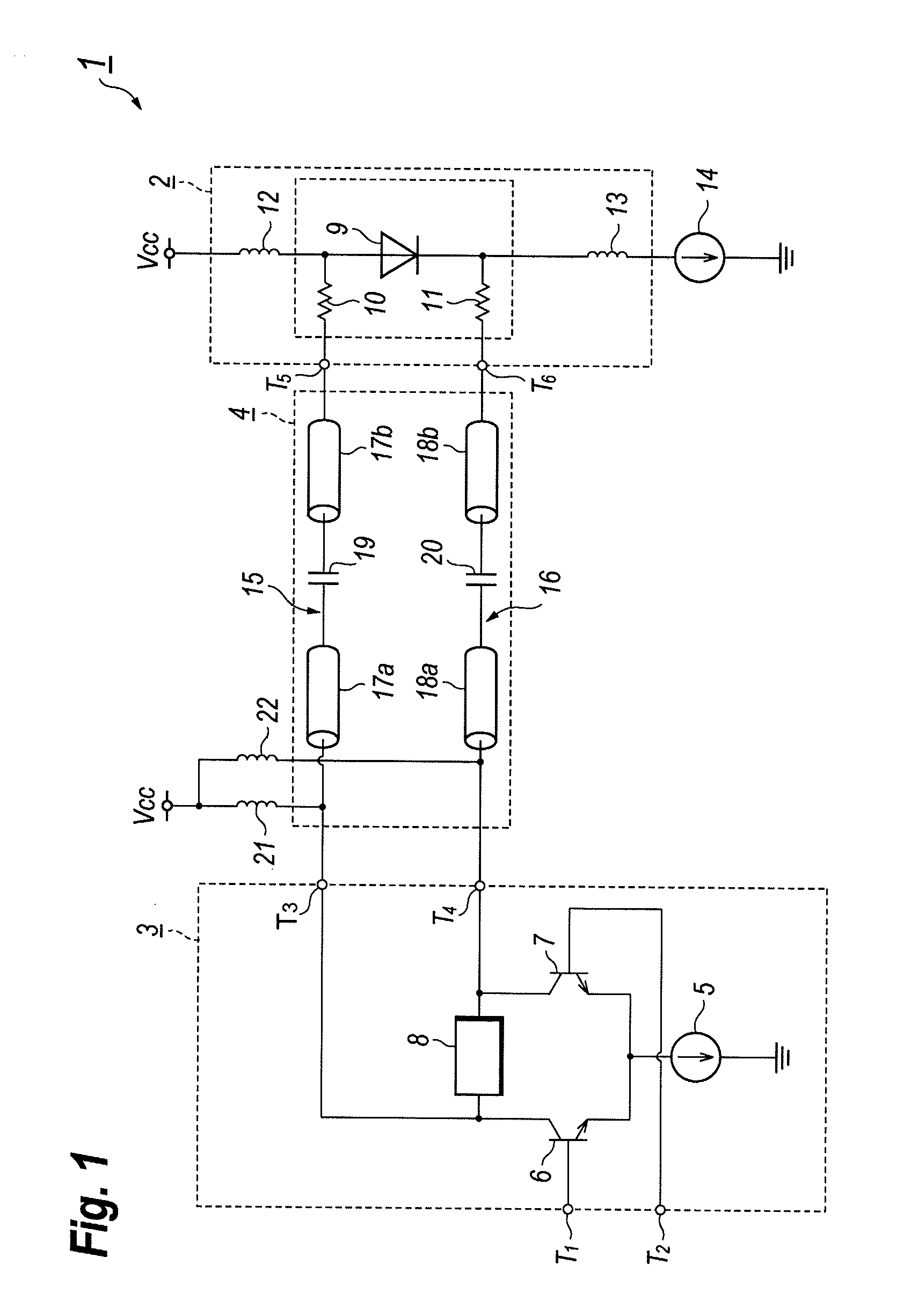
[0020]FIG. 1 is a circuit diagram of an optical transmitter 1 according to the first embodiment of the present invention. The optical transmitter 1 is an apparatus to generate an optical signal corresponding to the data to be transmitted in the optical communication system, and includes a transmitter optical subassembly 2 (hereafter denoted as TOSA), a LD-Driver 3, and a transmission network 4 that couples the LD-driver 3 with the TOSA 2.

[0021]The data to be transmitted is provided in the input terminals, T1 and T2, as the configuration of the differential signals, TxN and TxP, respectively. Two transistors, 6 and 7, which constitutes a differential circuit with a modulation current source 5, each receives the data provid...


PUM


Abstract

An LD-Driver with a back termination circuit is disclosed. The back termination circuit of the invention provides a transistor as an active device, a current source to provide a bias current to the transistor, and a resistor as a passive element that couples the transmission lines carrying a differential signal thereon. Because the transistor shows a differential resistance of several tens of ohms by providing only a few milli-amperes, the output impedance of the LD-Driver may be substantially matched with the characteristic impedance of the transmission line with lesser additional power consumption.

Description

BACKGROUND OF THE INVENTION[0001]1. Field of the Invention[0002]The present invention relates to a laser diode driver (hereafter denoted as LD-Driver) that drives a semiconductor laser diode (hereafter denoted as LD), and an optical transmitter providing the LD-Driver.[0003]2. Related Prior Art[0004]An ordinary LD applicable to the optical communication system has a differential resistance of 5 to 10Ω. Such an LD is enclosed within a coaxial CAN package and driven by the LD-Driver by being provided with a driving current thorough a transmission line formed on, for instance, a flexible printed circuit board and a rigid circuit board. Because a distance between the LD-Driver and the LD is a few tens of milli-meters, the driving signal degrades due to the signal reflection between the transmission line and the LD or between the transmission line and the LD-Driver as the transmission rate of the optical communication becomes faster.[0005]Various prior arts have reported the back termina...

Claims


Application Information

Patent Timeline
IPC IPC(8): H04B10/04H01S3/10H01L33/00H01S5/042H04B10/2507H04B10/40H04B10/50H04B10/60
CPCH01S5/042H04B10/504
Inventor TANAKA, KEIJI
Owner SUMITOMO ELECTRIC IND LTD
Why Eureka
Try Eureka