Electrodynamic Control of Blade Clearance Leakage Loss in Turbomachinery Applications

a technology of electric motor and blade, applied in the direction of machines/engines, mechanical equipment, liquid fuel engines, etc., can solve the problem of typical efficiency loss of turbines, and achieve the effect of efficient energy exchang

Active Publication Date: 2010-07-22
UNIV OF FLORIDA RES FOUNDATION INC
View PDF8 Cites 56 Cited by
  • Summary
  • Abstract
  • Description
  • Claims
  • Application Information

AI Technical Summary

Problems solved by technology

A turbine typically experiences efficiency loss due to fluid leakage through a clearance gap between a turbine blade and a casing wall in a turbine stage.

Method used


Image

  • Electrodynamic Control of Blade Clearance Leakage Loss in Turbomachinery Applications
  • Electrodynamic Control of Blade Clearance Leakage Loss in Turbomachinery Applications
  • Electrodynamic Control of Blade Clearance Leakage Loss in Turbomachinery Applications

Examples


Embodiment Construction

[0011]Embodiments of the subject invention utilize electrohydrodynamic (EHD) effects to control and / or reduce leakage flow in turbomachinery applications. In specific embodiments, electrodynamic effects are used to control leakage flow through gas turbine tips. Additional embodiments can control leakage flow through compressors or diffuser vanes, where diffuser vanes guide flow via quasi-static blades. Embodiments of the invention can be incorporated with high and low pressure turbines. Embodiments of the present invention can be useful as devices for use in power generation and the aircraft industry. In addition, embodiments providing a non-contact way to control leakage loss may be useful in many areas. Embodiments can also be utilized for controlling flow energy losses in diffusers.

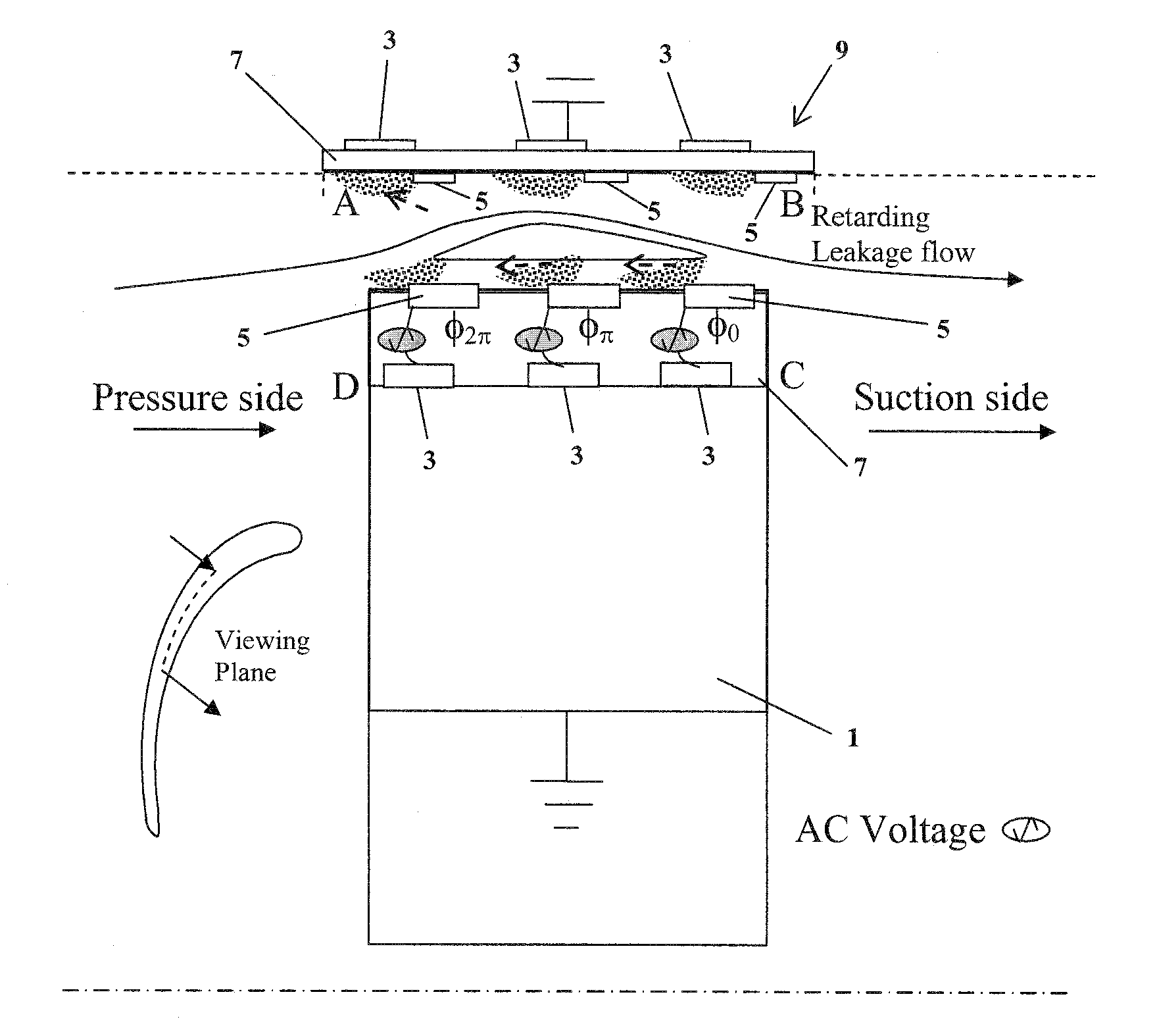
[0012]A schematic for the electrodynamic flow about the turbine tip in accordance with an embodiment is shown in FIG. 1, showing blade tip electrodes and illustrating a flow actuation mechanism inside ...


PUM


Abstract

Electrodynamic control of fluid leakage loss is provided. Embodiments utilize electrohydrodynamic (EHD) principles to control and / or reduce leakage flow in turbomachinery. Electrodes can be used to provide a flow actuation mechanism inside the clearance gap for generating discharge. The electrodes can be positioned to have geometric asymmetry. Embodiments provide the electrodes on a turbine blade. The blade can have a DC power that can function as a square pulsed DC wave with the duty cycle equal to the blade passing frequency and the stator can be grounded. In an embodiment, the stator can have the actuator of the electrode-insulator assembly attached to the inside. In one embodiment, the actuators can be arranged just on the stator or casing. The phase and power supply to individual electrodes can be adapted as needed. In one embodiment, the phase can be lagged for accurate control of leakage flow. The control of the power supply to the electrodes can involve a closed control loop that monitors tip gap size.

Description

CROSS-REFERENCE TO RELATED APPLICATION [0001]The present application claims the benefit of U.S. Provisional Application Ser. No. 60 / 943,099, filed Jun. 11, 2007, which is hereby incorporated by reference herein in its entirety, including any figures, tables, or drawings.BACKGROUND OF INVENTION [0002]In general, a turbine engine extracts energy from fluid flow. The fluid may be gas, steam, or liquid. One interest in turbine design is to provide high efficiency for energy generation. A turbine typically experiences efficiency loss due to fluid leakage through a clearance gap between a turbine blade and a casing wall in a turbine stage. This gap between the turbine blade tip and the casing is often referred to as a tip gap. The tip gap allows for the blade's mechanical and thermal growth, but the tip gap leakage flow results in a reduction in the work done by the blade and, therefore, the efficiency of the turbine.[0003]Some approaches to improving the turbine efficiency include reduci...

Claims


Application Information

Patent Timeline
Patent Type & Authority Applications(United States)
IPC IPC(8): F01D11/08
CPCF01D5/20Y02T50/673F05D2270/172F01D11/10Y02T50/60
Inventor ROY, SUBRATA
Owner UNIV OF FLORIDA RES FOUNDATION INC
Why Eureka
Try Eureka