
Bone Implant, and Set for the Production of Bone Implants

a bone implant and set technology, applied in the field of bone implants and set for the production of bone implants, can solve the problems of inability to develop and manufacture bone implants with the aforementioned properties, lack of biomechanical adaptation, and inability to resorb the described material and in particular the aforementioned manufacturing process

Inactive Publication Date: 2010-07-22
NIES BERTHOLD
View PDF17 Cites 22 Cited by
  • Summary
  • Abstract
  • Description
  • Claims
  • Application Information

AI Technical Summary

Benefits of technology

[0016]The goal of the present invention is therefore to provide a bone replacement material that, on the one hand, has the mechanical performance and in particular the great mechanical adaptability of cellular metal structures to biomechanical requirements of the bone regeneration and, on the other hand, utilizes the regeneration-stimulating potential of nano-structured bone minerals.

Problems solved by technology

For this purpose, the network is filled with the matrix materials or their precursors and matrix material and network are exposed to a temperature increase >600° C. Even though as a possible application the use as bone implant is mentioned, the described material and in particular the aforementioned manufacturing process is entirely unsuitable for development and production of bone implants with the aforementioned properties.
Further disadvantages in case of the sintered hydroxyl apatite as a matrix is the lack of resorption capability, the undefinable composition of the integral connection of the metal and matrix (that in case of medicinal application is to be viewed as very critical), and the lack of a possibility for biomechanical adaptation (the sintered product according to the claimed manufacturing process always results in a material with extremely high stiffness that, as in the case of sintered hydroxyl apatite is a multiple of that of bone).
The aforementioned material has therefore in relation to bone implants no advantages but instead rather disadvantages in regard to the older prior art (solid metal implants).

Method used


Image

  • Bone Implant, and Set for the Production of Bone Implants
  • Bone Implant, and Set for the Production of Bone Implants
  • Bone Implant, and Set for the Production of Bone Implants

Examples


example 1

Bone Implant on the Basis of a Metal Foam Filled with Nano-Crystalline Hydroxyl Apatite

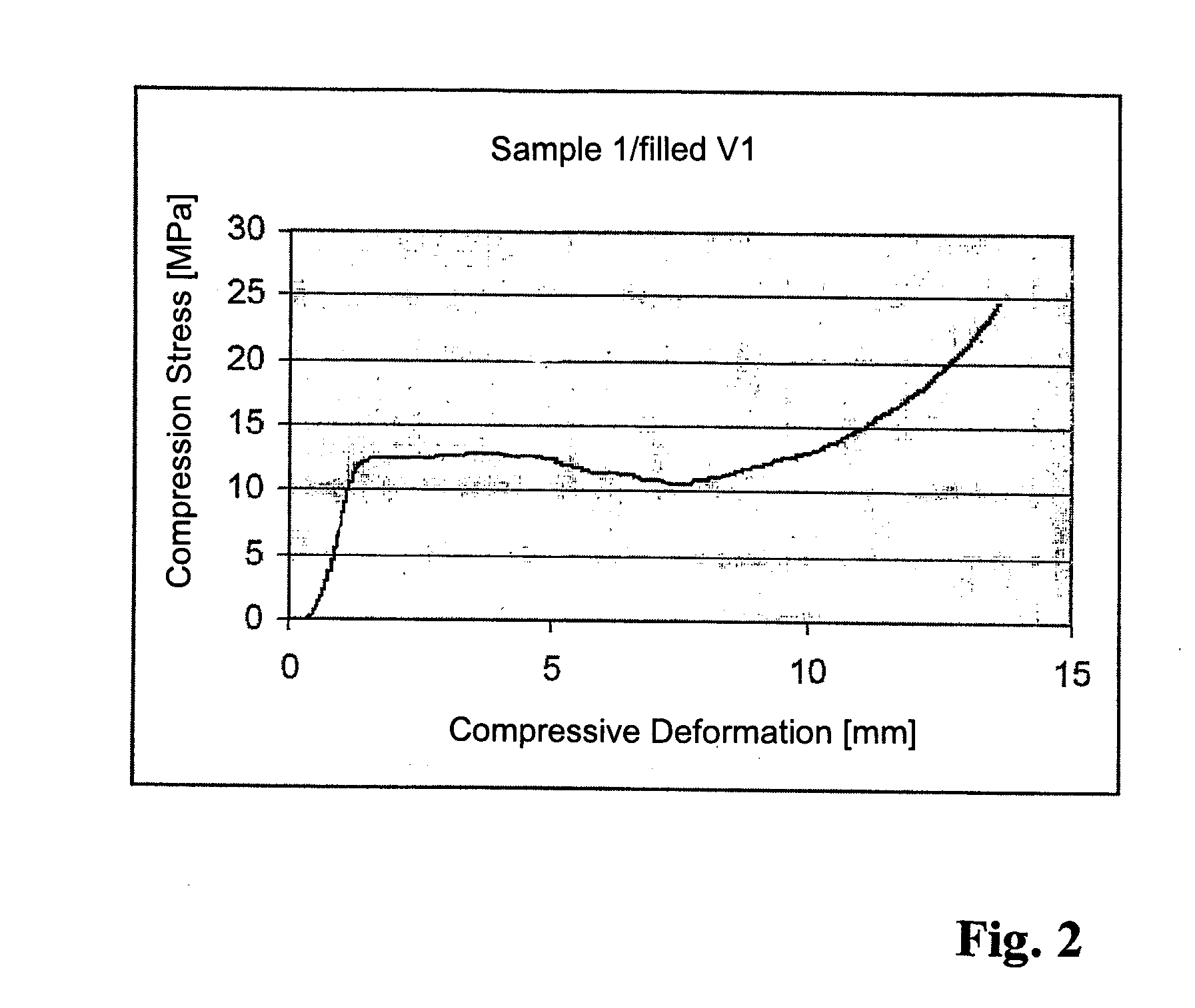
[0080]A metal foam of implant steel (360 L) is used that is produced by Fraunhofer Institut für Verfahrenstechnik and angewandte Materialforschung (IFAM Dresden, Adler et at, Sintered Open-Celled Metal Foams Made by Replication Method—“Manufacturing and Properties on Example of 316L Stainless Steel Foams”, in Cellular Metals and Polymers 2004, edited by R. F. Singer, et al, and John Banhart “Manufacture, characterisation and application of cellular metals and metal foams”; in Progress in Materials Science 46 (2001) 559-632) according to a powder-metallurgical method (pore size approximately 45 ppi / “pores per inch”). As a nano-crystalline hydroxyl apatite preparation a pasty preparation with 35% solids contents (in aqueous preparation) is employed.

[0081]The metal foam (diameter 3 cm, height 1 cm) is positioned on a filter paper above a glass frit in a tightly fitting plastic pipe (height 3 cm). Ont...

example 2

Bone Implant of the Basis of Metal Foam Filled with Calcium Phosphate Cement

[0083]The same metal foam as disclosed in Example 1 is used. As a filler calcium phosphate cement of own production with the following composition is used:

Powder Component:

[0084]60% TCP (fired at 1300 ground to a particle size of [0085]26% calcium hydrogen phosphate (anhydrous CaHPO4 [0086]10% calcium carbonate (CaCO3)[0087]4% hydroxyl apatite (precipitated),

all components are intensively mixed and ground together.

[0088]As a mixing solution, to a 2% sodium hydrogen phosphate (Na2HPO4) solution phosphoserine in a concentration of 50 mmol / l is added and subsequently the pH value is adjusted to 8.5. Subsequently, the powder component is homogeneously mixed with this mixing solution in a powder / liquid ratio of 0.7 at a temperature of 10° C. The obtained paste is uniformly applied onto the metal foam in an experimental set-up according to the Example 1 (without filter paper and glass frit in an airtightly sealabl...

example 3

Bone Implant on the Basis of a Hollow Sphere Metal Structure Filled with Nano-Crystalline Hydroxyl Apatite

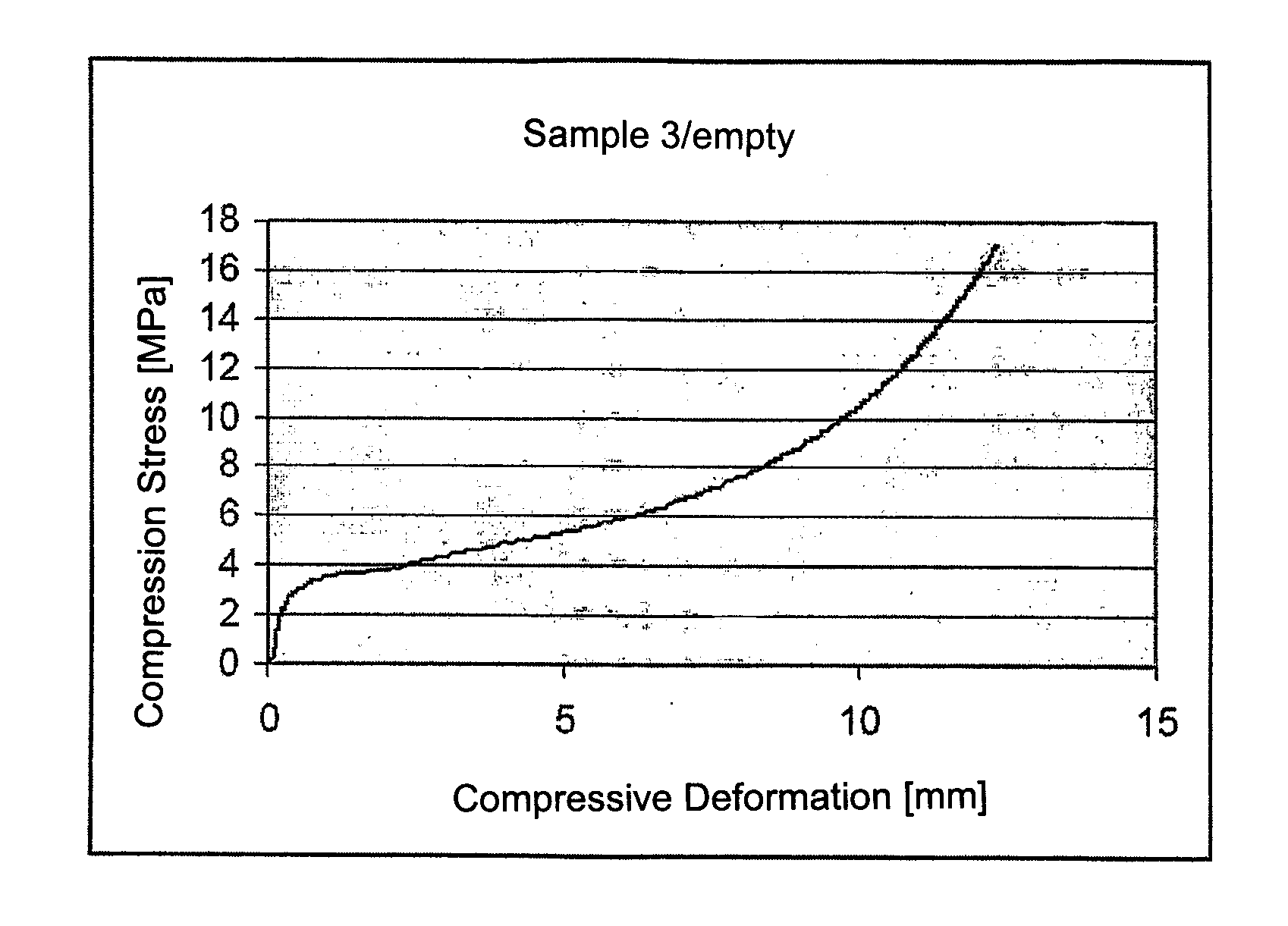
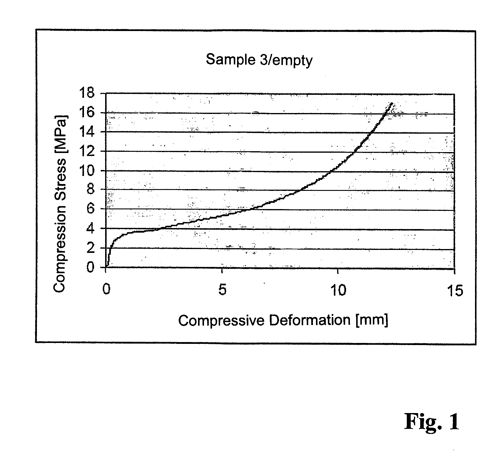
[0090]As a porous metal structure cylinders of a diameter of 3 cm, height of 1 cm, are used that are comprised of hollow metal spheres, sintered together, with a size of the individual spheres of 1 mm in diameter. The employed material is implant steel (316 L) produced by Fraunhofer Institut für Verfahrenstechnik and angewandt Materialforschung (IFAM Dresden) in accordance with a powder-metallurgical method. In the same experimental set-up as in 1, a paste of nano-crystalline hydroxyl apatite with a solids content of 35% is introduced into the pore system of the metal cylinder. After loading the same procedure as in Example 1 is followed.


PUM

PropertyMeasurementUnit
flexural strengthaaaaaaaaaa

Abstract

The invention relates to bone implants and sets for producing bone implants. Said bone implants are made from pasty or cementitious preparations which are introduced into open-cell metal structures comprising an interconnected pore system as solid or porous materials and are optionally allowed to set, the metal structure per se being biocompatible in biological conditions and being stable or corrodible. The bone implant according to the invention contains at least one open-cell metal structure that has an interconnected pore system which is at least partially filled with a preparation made of at least one bone replacement material. The open-cell metal structure is significantly less rigid than the solid material made of the same metal.

Description

[0001]The invention concerns bone implants and sets for producing bone implants. They are comprised of bone replacement materials on the basis of nano-crystalline calcium phosphates that, as solid or porous material, are introduced into open-cell metal structures with an interconnecting pore system and optionally cured, wherein the metal structure itself is biocompatible under biological conditions and may be stable or corrodible.BACKGROUND[0002]As bone replacement materials for reconstruction of defective bone structures large quantities of biogenic bone materials are still used, i.e., body-own bone and donor bone, even though harvesting of such materials is connected with significant side effects and risks and they are in no way standardized Synthetic alternative products comply with the quality requirements of medicinal product laws or corresponding regulations outside of Europe but are often, rightly or wrongly, viewed as inadequate compared to biogenic materials. The quantitati...

Claims


Application Information

Patent Timeline
Patent Type & Authority Applications(United States)
IPC IPC(8): A61F2/28
CPCA61F2/0095A61F2/28A61F2/30767A61F2/3094A61F2002/2817A61F2002/30011A61F2002/30062A61F2002/30092A61F2002/30677A61F2002/3092A61F2210/0004A61F2210/0014A61F2250/0023A61F2310/00011A61F2310/00017A61F2310/00023A61F2310/00029A61F2310/00041A61F2310/00095A61F2310/00113A61F2310/00125A61F2310/00131A61F2310/00155A61F2310/00293A61F2310/00365A61F2310/00383A61F2310/00395A61L27/04A61L27/12A61L27/30A61L27/54A61L27/56A61L2300/404A61L2300/41A61L2300/412A61L2300/602A61L2430/02
Inventor NIES, BERTHOLD
Owner NIES BERTHOLD
Learn More