
Electronic circuit

a technology of electronic circuits and circuits, applied in pulse generators, instruments, pulse techniques, etc., can solve the problems of timepiece malfunctions and increased power consumption of microcomputers

Active Publication Date: 2010-07-29
SEMICON COMPONENTS IND LLC
View PDF4 Cites 11 Cited by
  • Summary
  • Abstract
  • Description
  • Claims
  • Application Information

AI Technical Summary

Benefits of technology

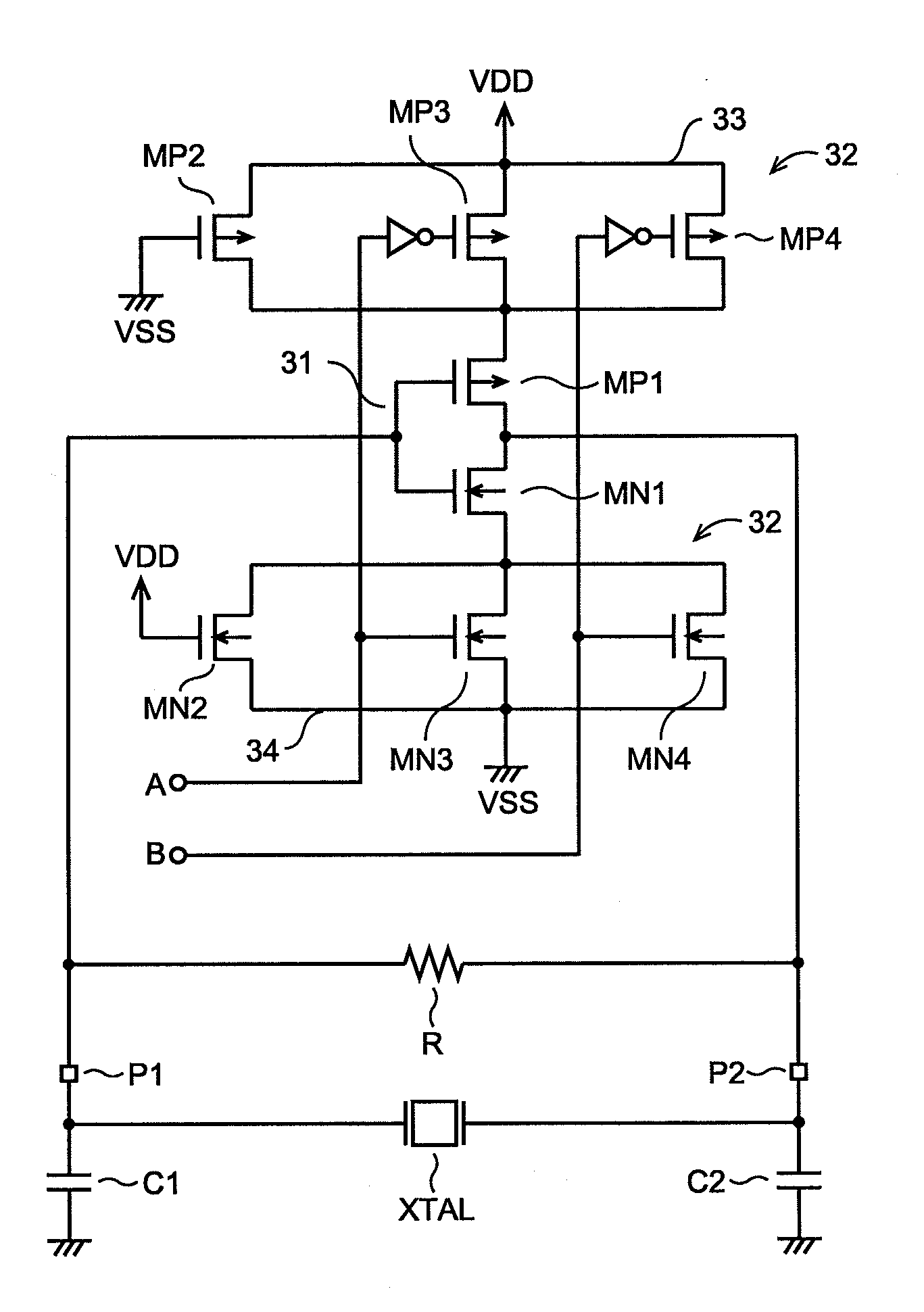
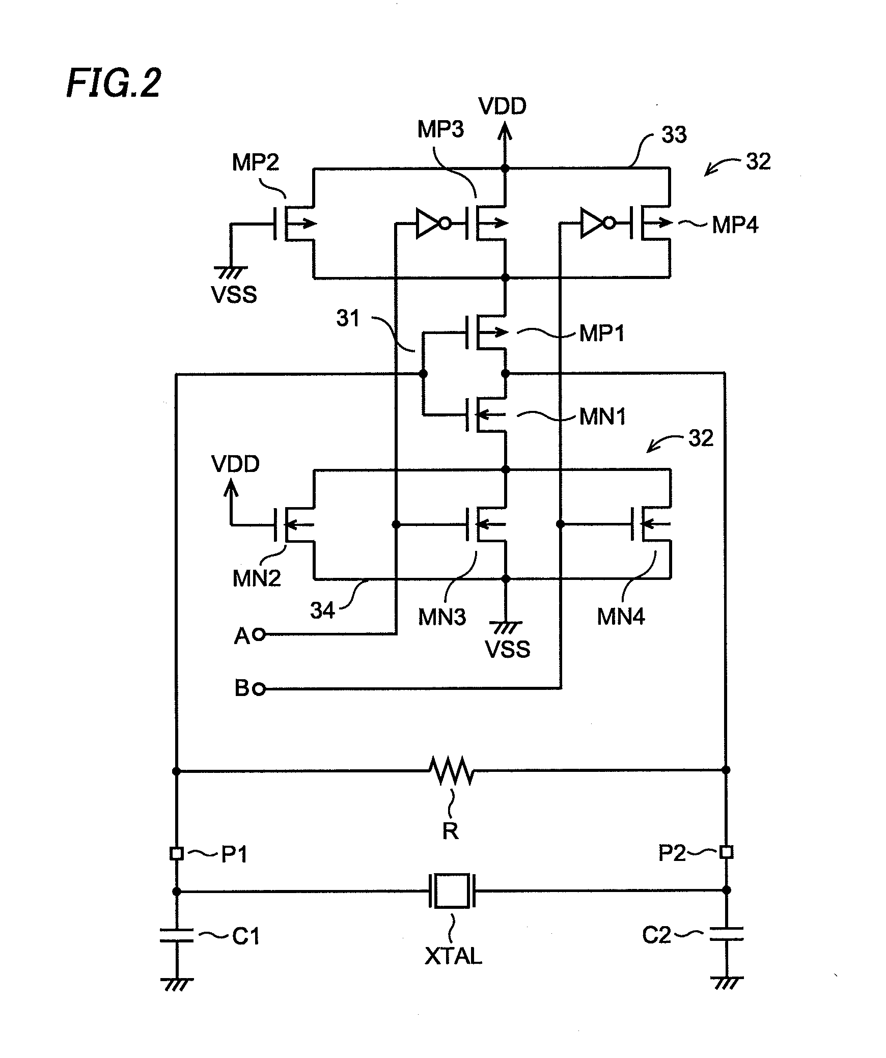
[0052]According to the embodiment of this invention, it is made possible to reduce the power consumption of the electronic circuit (microcomputer, for example) while preventing the malfunctioning of the low frequency oscillator by appropriately setting the power supply impedance of the low frequency oscillator corresponding to the operation mode.

Problems solved by technology

When the power supply impedance of the timepiece oscillator is set to be high, however, there is caused a problem that the timepiece would malfunction since a noise caused from the high frequency system clock oscillator is so large in the high speed operation mode to exert an influence on the clock generated by the timepiece oscillator.
When the power supply impedance of the timepiece oscillator is set to be low as a countermeasure against the noise, on the other hand, there is caused another problem that the power consumption of the microcomputer is increased.

Method used


Image

  • Electronic circuit
  • Electronic circuit
  • Electronic circuit

Examples


Embodiment Construction

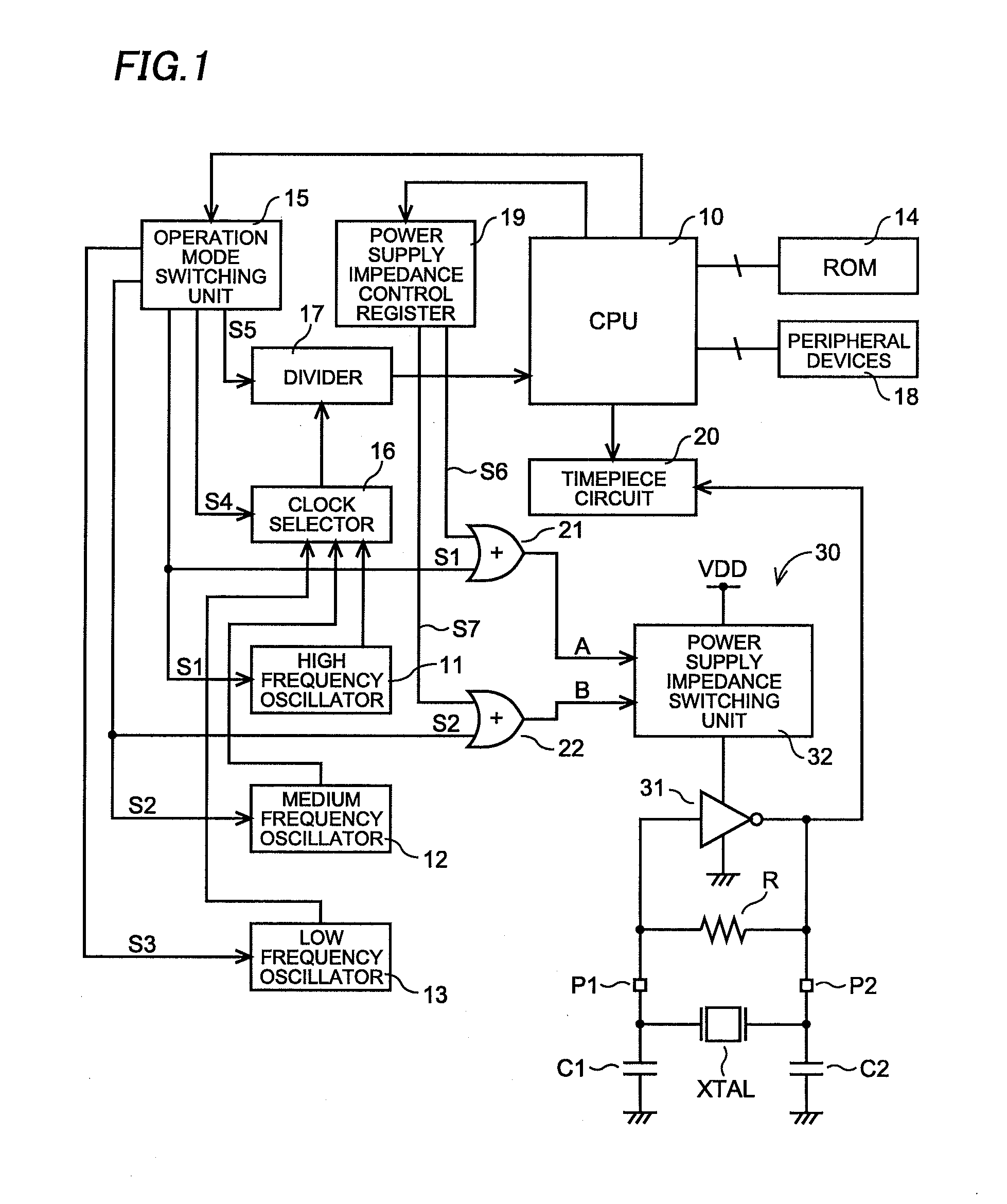
[0016]A microcomputer according to an embodiment of this invention will be described referring to FIGS. 1 through 4. First, an overall structure of the microcomputer will be described referring to FIG. 1.

[0017]A high frequency oscillator 11 that generates a high frequency clock (8 MHz, for example), a medium frequency oscillator 12 that generates a medium frequency clock (4 MHz, for example) and a low frequency oscillator 13 that generates a low frequency clock (1 MHz, for example) are provided as sources of system clocks, as shown in FIG. 1. Each of the three oscillators 11, 12 and 13 is an RC oscillator that is formed including a resistor R and a capacitor C, for example.

[0018]Starting and halting of the three oscillators 11, 12 and 13 are controlled by a CPU 10. That is, the CPU 10 controls an operation mode switching unit 15 in accordance with a program stored in a ROM (Read Only Memory) 14. The operation mode switching unit 15 outputs corresponding each of control signals S1, S...


PUM


Abstract

This invention makes it possible to reduce a power consumption of an electronic circuit (microcomputer, for example) while preventing malfunctioning of an oscillator by appropriately setting a power supply impedance of a low frequency oscillator corresponding to an operation mode. A high frequency oscillator, a medium frequency oscillator and a low frequency oscillator are provided as sources of system clocks. In addition, there is provided a quartz oscillator to generate a clock for a timepiece. When the high frequency oscillator is in operation, a power supply impedance of the quartz oscillator is reduced to improve a noise tolerance. In a waiting period during which the high frequency oscillator, the medium frequency oscillator and the low frequency oscillator are halted, on the other hand, the power supply impedance of the quartz oscillator is increased to suppress the power consumption.

Description

CROSS-REFERENCE OF THE INVENTION[0001]This application claims priority from Japanese Patent Application No. 2009-016646, the content of which is incorporated herein by reference in its entirety.BACKGROUND OF THE INVENTION[0002]1. Field of the Invention[0003]This invention relates to an electronic circuit, specifically to an electronic circuit having a plurality of oscillators different in oscillation frequency from each other.[0004]2. Description of the Related Art[0005]A conventional microcomputer is provided with a system clock oscillator that generates a clock (system clock or the like) for operations of internal circuits such as a CPU (Central Processing Unit) and a timepiece oscillator that generates a clock for a timepiece. In general, the timepiece oscillator is formed of a quartz oscillator and generates a clock of a low frequency (32 KHz, for example) compared with a frequency of the clock generated by the system clock oscillator.[0006]The microcomputer generally has a plur...

Claims


Application Information

Patent Timeline
IPC IPC(8): H03K3/01H03B5/30
CPCG06F1/32G06F1/324H03B5/364Y02B60/1217H03B2200/0046H03B2200/0062H03B2200/0012Y02D10/00
Inventor KONDO, HIDEO
Owner SEMICON COMPONENTS IND LLC
Learn More