Device for aspirating fluids

a technology of aspirating fluid and subretinal fluid, which is applied in the field of aspirating fluid devices, can solve the problems of atrophy of the sensory retina, vision loss, and each of the above procedures does not provide immediate repositioning of the detached retina to the underlying tissues

Inactive Publication Date: 2010-07-29
ISCI INTERVENTIONAL CORP
View PDF99 Cites 48 Cited by
  • Summary
  • Abstract
  • Description
  • Claims
  • Application Information

AI Technical Summary

Benefits of technology

[0015]In one embodiment the device further comprises one or more fenestrations in the second elongated tubular member that extends beyond the open distal end of the first elongated tubular member. Typically the fenestrations have a maximum diameter of in the range of about 0.0005 inch to about 0.005 inch. Typically the centers of one or more fenestrations are a distance from the distal end of the second elongated tubular member in the range from about 0.001 inch to about 0.01 inch.
[0016]In another embodiment the device further comprises a blocking member disposed in the annular space at the distal end of the device, the blocking member having a configuration sufficient to substantially prevent the ingress of tissues into the annular space through the open distal end without preventing fluid flow through the annular space. The blocking member may typically comprise a coil, a loop or a perforated sheet. In a perforated sheet the perforations typically have average diameters in the range from about 0.0001 inch to about 0.005 inch.

Problems solved by technology

Chronic separation between the sensory retina and the underlying RPE can deprive the sensory retina of nutrients and oxygen, causing the sensory retina to atrophy with resultant vision loss.
Each of the above procedures does not provide immediate re-apposition of the detached retina to the underlying tissues.
Failure to provide immediate re-apposition can result in the use of uncomfortable implants that limit the range of eye motion and produce long reabsorption rates of the SRF by the tamponade effect.
However, this method can fail due to the properties of the sensory retinal tissue.
Another failure mode may be attributed to kinking of the micro needle.
While accessing the subretinal space, the micro needle may be bent when encountering tissues, kinking the shaft and reducing its effective vacuum and ability to aspirate the SRF.

Method used


Image

  • Device for aspirating fluids
  • Device for aspirating fluids
  • Device for aspirating fluids

Examples


example 1

Aspiration Device

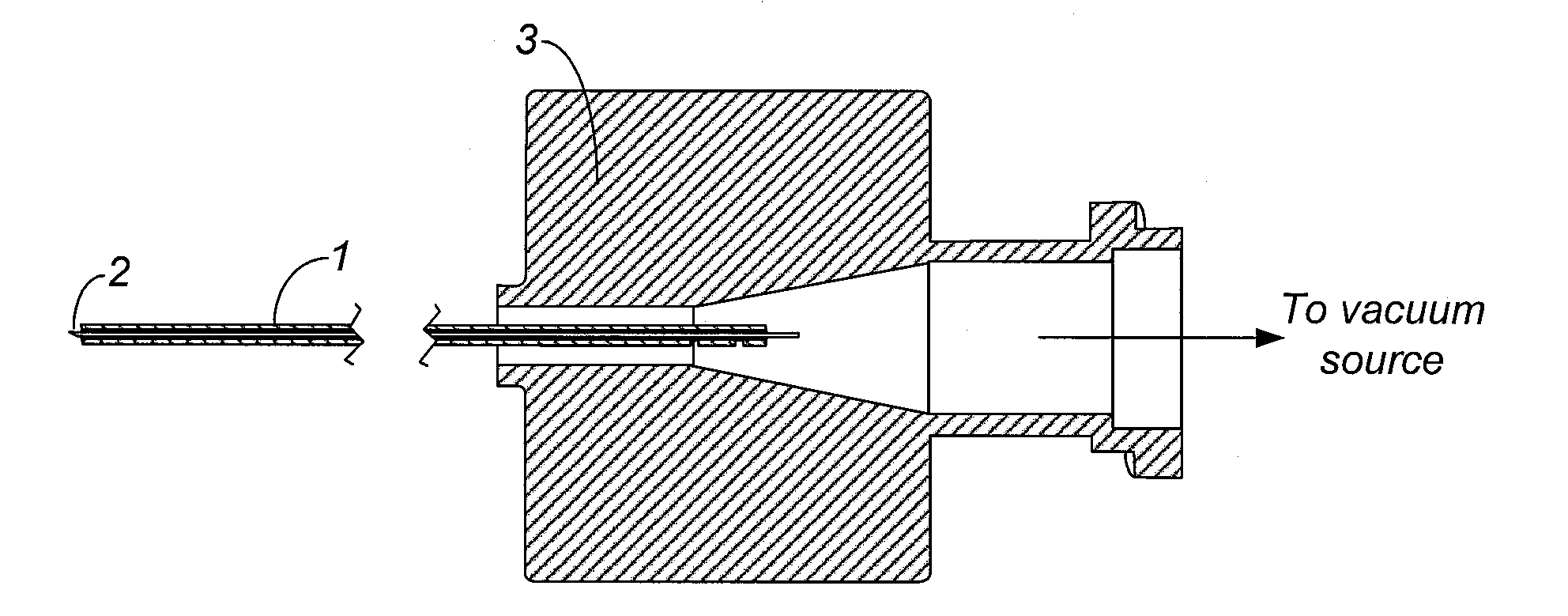
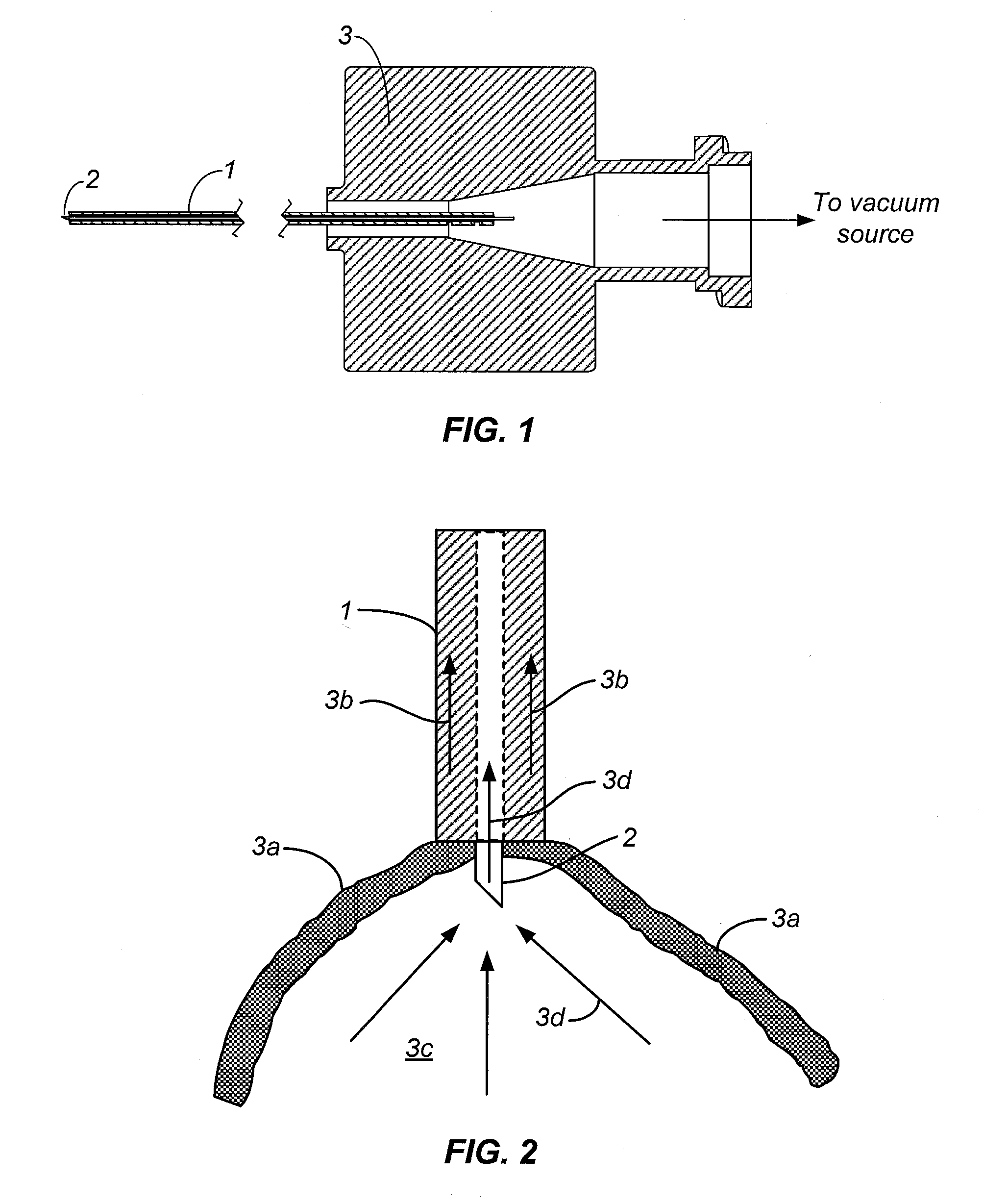
[0068]A 25 gauge stainless steel hypotube (Small Parts, Inc) was used as the main shaft. Two holes were drilled at distances of 0.05″ and 0.12″ from the proximal edge of the hypotube. A third hole was drilled 1.15″ from the distal edge of the hypotube. A second 25 gauge stainless steel hypotube (Small Parts, Inc) was laser welded at an angle to provide a flow path to the third hole.

[0069]A polyimide tube with a lumen of 100 microns, an outer diameter of 125 microns, and a length of 0.25″ (Microlumen, Inc) was inserted for a distance of 0.05″ into another polyimide tube with a lumen of 165 microns, an outer diameter of 210 microns, and a length of 1.45″. Cyanoacrylate adhesive (Loctite 4011, Loctite, Inc) was applied to bond the two polyimide tubes together.

[0070]A nitinol coil with a length of 0.165″ and outer diameter of 250 microns was made on a coil winder using nitinol wire with a diameter of 0.0015″ (Fort Wayne Metals, Inc). The nitinol coil was placed over pol...

example 2

Laboratory Testing with the Aspiration Device

[0073]A human cadaver eye was obtained from an eye bank. The cornea, the iris, the lens, and the vitreous were removed, providing access to the retina from the interior of the globe without significantly damaging the retina tissue, while also allowing for the retina to retain its original physiological attachments. Using existing post-mortem retinal detachments or creating a retinal detachment using phosphate-buffered saline injected through a needle inserted through the exterior of the globe into the subretinal space, experiments were conducted using the prototype.

[0074]The aspiration device from Example 1 was inserted into the subretinal space and a vacuum level in the range of 300 mm Hg to 600 mm Hg was applied. The retinal tissue was visibly captured by the outer annular vacuum, while fluid and tissue debris visibly migrated towards the micro needle. The device was capable of aspirating SRF until the re-apposition of the sensory retin...

example 3

An Aspiration Device with External Tissue Guard

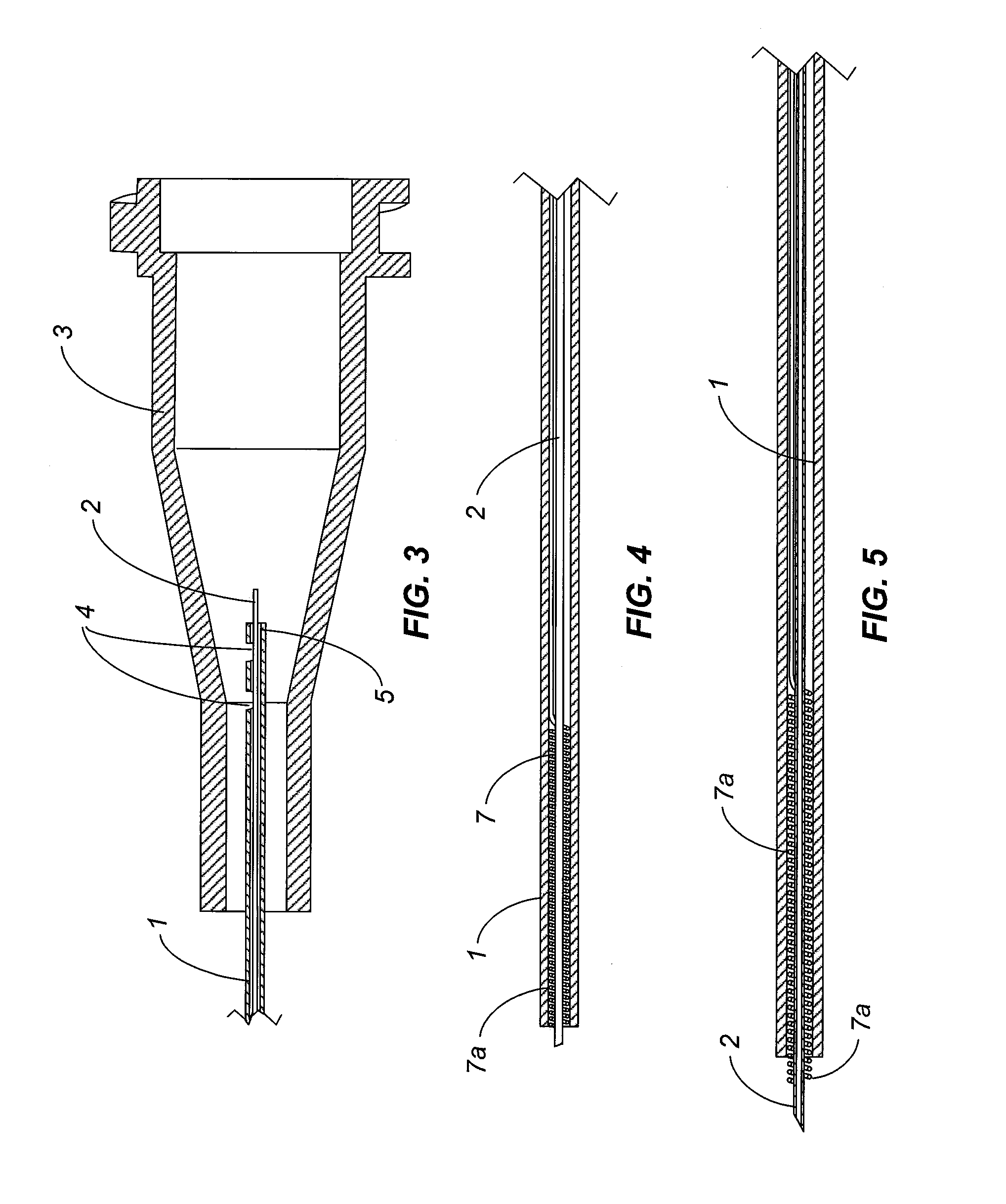
[0075]A 25 gauge stainless steel hypotube (Small Parts, Inc) was used as the main shaft and cut to a length of 1.25″. A 0.25″ length of polyimide tubing with an inner diameter of 0.0044″ and an outer diameter of 0.0056″ (Microlumen, Inc.) was used as the micro needle. Cyanoacrylate adhesive (Loctite 4011, Loctite, Inc.) was used to bond the micro needle within the main shaft, such that 0.20″ of the micro needle protruded from the main shaft. UV cure epoxy (Loctite 3341, Loctite, Inc.) was applied near the distal opening of the micro needle in the shape of a disc 360 degrees around the micro needle to act as a tissue guard. The disc had a diameter of 0.012″.


PUM


Abstract

Surgical devices are provided for aspiration of the subretinal fluid (SRF) of the eye in a retinal detachment that allows re-apposition of the sensory retina to the underlying RPE. The device is connected to a vacuum source, introduced into the posterior chamber through a sclerostomy port and placed against the detached retinal tissue. The device pulls on and captures the surface of the sensory retina, causing a micro needle to pierce through the tissue. As the sensory retina is captured and held in place by the vacuum, a protected pocket is created and the tissue is prevented from folding onto itself and occluding the micro needle tip.

Description

CROSS-REFERENCE TO RELATED APPLICATION [0001]This application is related to co-pending, commonly assigned Ser. No. ______, filed on an even date herewith, entitled “Subretinal Access Device” in the names of Ho, Friedrich; Conston, Stanley R. and Yamamoto, Ronald.FIELD OF THE INVENTION [0002]The present invention relates to devices for aspiration of the subretinal fluid (SRF) of the eye in a retinal detachment that allows re-apposition of the sensory retina to the underlying RPE.BACKGROUND OF THE INVENTION [0003]A retinal detachment occurs when subretinal fluid (SRF) causes separation between the sensory retina and the supporting outer tissues, which consist of the retinal pigment epithelium (RPE) and choroid. Typically, retinal detachments are caused when a full-thickness defect in the sensory retina allows for SRF to access the subretinal space. This SRF is derived from liquefied vitreous humor (the transparent gel that occupies the posterior segment of the eye), and full-thickness...

Claims


Application Information

Patent Timeline
Patent Type & Authority Applications(United States)
IPC IPC(8): A61F9/00A61F2/958
CPCA61F9/00727A61M2210/0612A61M1/0084A61F9/00736A61M1/85A61F9/007A61M1/00A61M15/00A61M27/00
Inventor CHANG, TOM S.HO, FRIEDRICHCONSTON, STANLEY R.YAMAMOTO, RONALD K.
Owner ISCI INTERVENTIONAL CORP
Why Eureka
Try Eureka