
Shift control device for vehicular continuously variable transmission

a technology of continuously variable transmission and control device, which is applied in the direction of mechanical equipment, digital data processing details, instruments, etc., can solve the problems of poor ride quality, no favorable acceleration is necessarily obtained, and the response of the vehicle to the increase of the speed is not good, so as to achieve excellent acceleration feeing, small running resistance, and large running resistance

Active Publication Date: 2010-07-29
TOYOTA JIDOSHA KK
View PDF2 Cites 12 Cited by
  • Summary
  • Abstract
  • Description
  • Claims
  • Application Information

AI Technical Summary

Benefits of technology

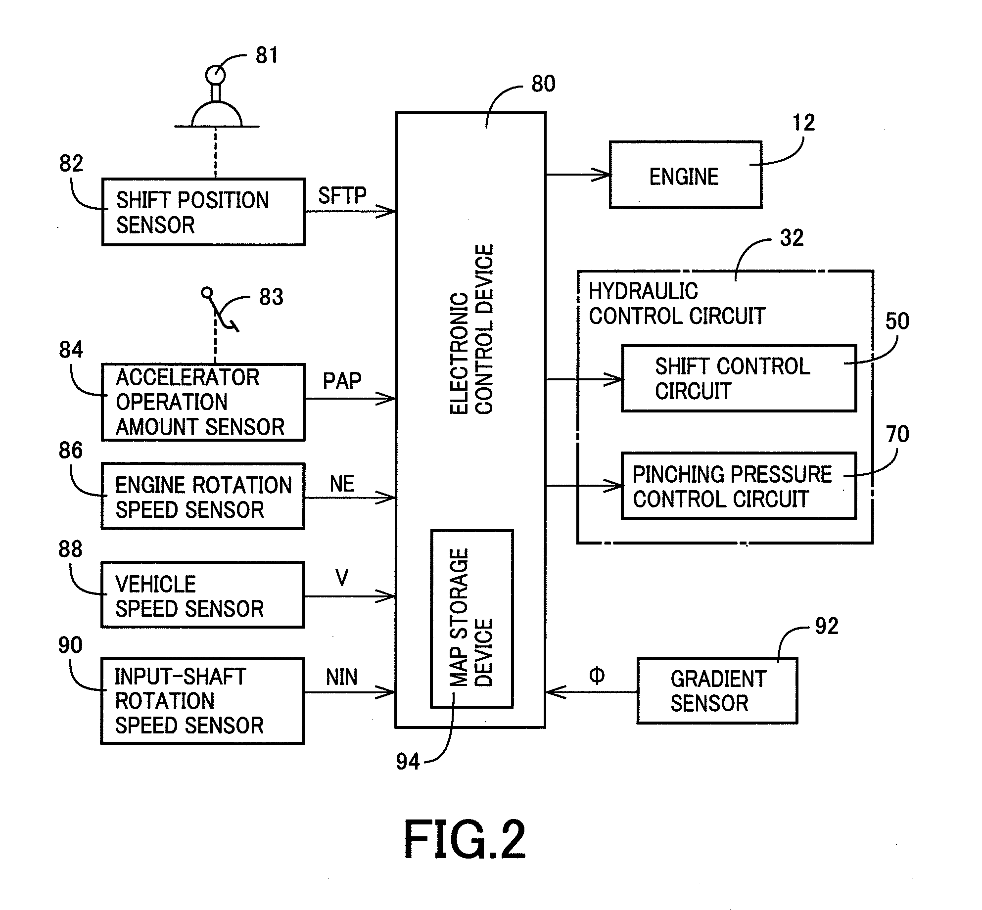
[0007]The present invention has been completed with the above view in mind, and has an object to provide a shift control device for a vehicular continuously variable transmission, arranged to switch a normal shift mode to an acceleration shift mode in response to an acceleration demand by a driver, which can prevent damage to running performance due to a transition to the acceleration shift mode during ascending road running or the like with increasing running resistance against a driver will.
[0011]A fourth aspect of the present invention is featured by, in anyone of the first to third aspects, that during the acceleration shift mode, a shift control is performed so as to cause the input-shaft rotation speed to be higher when the running resistance is larger than when the running resistance is smaller.
[0013]According to the shift control device for a vehicular continuously variable transmission of the first aspect, the acceleration demand determining value is determined depending on the running resistance of the vehicle such that the shift mode is more difficult to be switched to the acceleration shift mode when the running resistance is larger than when the running resistance is smaller. This prevents a drive mode from being switched to the acceleration shift mode under a drive (running) condition with a large running resistance during ascending road running or the like against the driver will. During the flat road running or the like with a small running resistance, the drive (running) mode is switched to the acceleration shift mode in response to the acceleration demand by the driver, resulting in excellent acceleration feeing and comfortable ride quality. Meanwhile, switching of the drive mode to the acceleration shift mode under the drive condition during ascending road running or the like with the large running resistance against the driver will is prevented, so that damage to running performance due to an inadequate drive force can be prevented.
[0014]According to the shift control device for a vehicular continuously variable transmission of the third aspect, during the acceleration shift mode, the shift control is performed so as to increase the input-shaft rotation speed in proportion to the increase in vehicle speed. During the flat road running or the like with a small running resistance, the drive mode is switched to the acceleration shift mode, resulting in excellent acceleration feeing. Meanwhile, this effectively prevents the switching of the shift mode to the acceleration shift mode against the driver will, under a drive condition in the presence of large running resistance with a slow increase of the vehicle speed or a decrease of the vehicle speed in reverse. Consequently, damage to running performance caused by a slow increase of the input-shaft rotation speed due to an increase delay of the vehicle speed can be prevented.
[0015]According to the shift control device for a vehicular continuously variable transmission of the fourth aspect, during the acceleration shift mode, the shift control is performed so as to cause the input-shaft rotation speed to be higher when the running resistance is larger than when the running resistance is smaller. Therefore, even if the shift mode is switched to the acceleration shift mode under the drive condition with large running resistance during ascending road running or the like, the input-shaft rotation speed is caused to increase accompanied by an increase in the rotation speed of the prime mover. This renders an increased drive force despite switching of the drive mode the acceleration shift mode, so that excellent running performance can be obtained even under the drive condition with large running resistance during ascending road running or the like.
[0016]According to the shift control device for a vehicular continuously variable transmission of the fifth aspect, the rise amount of the input-shaft rotation speed during the transition from the normal shift mode to the acceleration shift mode is larger when the running resistance is larger than when the running resistance is smaller. Therefore, even if the shift mode is switched to the acceleration shift mode under the drive condition during ascending road running or the like with large running resistance, the input-shaft rotation speed is increased accompanied by an increase in the rotation speed of the prime mover. This renders an increased drive force despite switching of drive mode the acceleration shift mode, so that excellent running performance can be obtained even under the drive condition with large running resistance during ascending road running or the like.

Problems solved by technology

However, taking time for the rotation speed to increase results in poor response up to increase of the vehicle speed.
This results in poor ride quality due to increased noise, and hence, no favorable acceleration is necessarily obtained.

Method used


Image

  • Shift control device for vehicular continuously variable transmission
  • Shift control device for vehicular continuously variable transmission
  • Shift control device for vehicular continuously variable transmission

Examples


embodiment

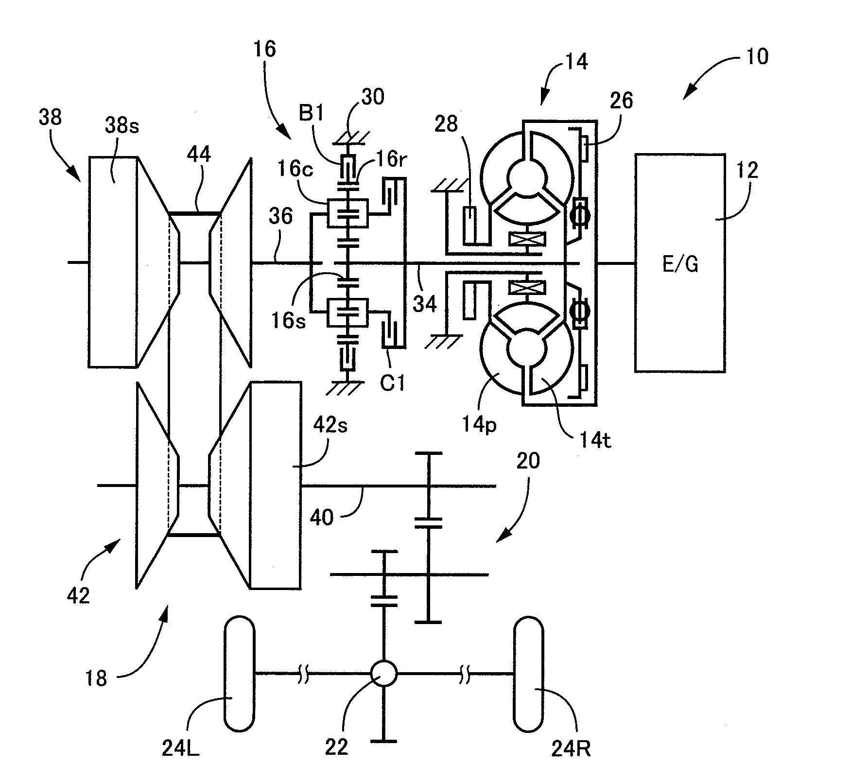
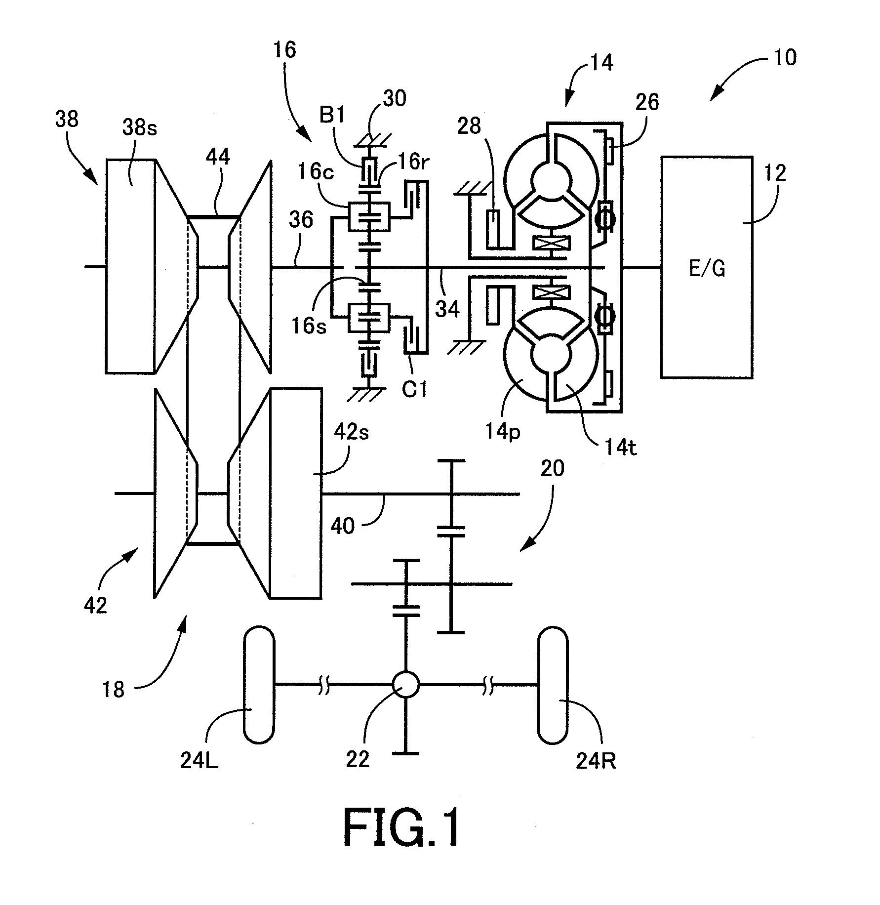
[0049]FIG. 1 is a skeleton view illustrating a vehicular drive apparatus 10 to which the present invention is applied. The vehicular drive apparatus 10 is of a transverse-mounted type preferably adopted in an FF (front engine and front drive) vehicle and includes an engine 12, such as an internal combustion engine like a gasoline engine and a diesel engine, etc., which serves as a drive-force source (prime mover) for driving a vehicle. The engine 12 generates an output, which is transferred from a torque converter 14 to a differential gear device 22 via a forward-drive / reverse-drive switching device 16, a belt-type continuously variable transmission (CVT) 18 and a reduction gear mechanism 20 for delivery to left and right drive wheels 24L and 24R.

[0050]The torque converter 14, corresponding to a hydraulic type power transfer device, includes a pump blade wheel 14p connected to a crankshaft of the engine 12 and a turbine blade wheel 14t connected to the forward-drive / reverse-drive sw...


PUM


Abstract

In a shift control device for a vehicular continuously variable transmission with an arrangement in which a normal shift mode is switched to an acceleration shift mode in response to an acceleration demand, a shift control is performed to prevent deterioration to running performance due to a transition to the acceleration shift mode by increased running resistance such as ascending road running or the like against a driver will.An acceleration demand determining value PAPL is set depending on a road surface gradient Φ such that the shifting mode is more difficult to be switched to the acceleration shift mode in a larger road surface gradient Φ, than in a smaller road surface gradient Φ. Such arrangement prevents the shift mode from being switched to the acceleration shift mode during ascending road running with an increase in an accelerator operation amount PAP against the driver will. During a flat road running with a small road surface gradient Φ, the shift mode is switched to the acceleration shift mode in response to the acceleration demand by the driver, thereby obtaining an excellent acceleration feeling. Meanwhile, the above arrangement prevents degradation of the ascending performance due to an inadequate drive force resulting from the shift mode switched to the acceleration shift mode during ascending road running against the driver will.

Description

FIELD OF THE INVENTION[0001]This invention relates to a shift control device for a vehicular continuously variable transmission, and more particularly, to improvement of the shift control device in which a shift control is performed with a normal shift mode switched to an acceleration shift mode in response to an acceleration demand of a driver.DESCRIPTION OF THE RELATED ART[0002]There has heretofore been known a shift control device for a vehicular continuously variable transmission including shift mode switching means arranged to determine as to whether an acceleration demand value of a driver exceeds a predetermined acceleration demand determining value upon which, when the acceleration demand value exceeds the acceleration demand determining value, a shift mode is switched from a normal shift mode to an acceleration shift mode. A shift control device, disclosed in Patent Publication 1, represents one example of such a shift control device wherein whether an acceleration demand i...

Claims


Application Information

Patent Timeline
IPC IPC(8): G06F19/00F16H59/18F16H59/44F16H59/66F16H61/02F16H61/66F16H61/662
CPCF16H59/18Y10T477/62427F16H2061/6611F16H59/66F16H61/16F16H2059/142F16H61/66259Y10T477/6242
Inventor TAMURA, TADASHIHINO, AKIRATAWARA, MASAHIROMATSUI, YASUNARI
Owner TOYOTA JIDOSHA KK
Learn More