Quantum key distribution system, optical transmitter, optical modulation control circuit, and optical modulation control method

a quantum key distribution system and quantum key control technology, applied in the field of optical modulation technique, can solve the problems of affecting the operation of optical modulation, the quantum state of the quantum key distribution system cannot be completely restored before observation, and the code-breaking using an enormous amount of calculations and new decryption algorithms is an ever present danger, so as to achieve stable optical modulation operation

Active Publication Date: 2010-08-05
NEC CORP
View PDF5 Cites 51 Cited by
  • Summary
  • Abstract
  • Description
  • Claims
  • Application Information

AI Technical Summary

Benefits of technology

[0032]According to the present invention, it is possible to detect, even in a low-intensity optical signal, the optical signal state after modulation as a detected photon number and control the operating point in light intensity modulation based on the detected pho...

Problems solved by technology

Although the rapidly growing Internet is convenient, there is great apprehension about its safety, and the need for an advanced cryptographic technique is intensifying to keep the confidentiality of communications.
However, these cryptographic methods guarantee the safety based on “complexity of calculations”.
Code-breaking using an enormous amount of calculations and new decryption algorithms is an ever present danger.
However, once the photons are observed, it is impossible to completely restore their quantum state before observation due to the Heisenber...

Method used


Image

  • Quantum key distribution system, optical transmitter, optical modulation control circuit, and optical modulation control method
  • Quantum key distribution system, optical transmitter, optical modulation control circuit, and optical modulation control method
  • Quantum key distribution system, optical transmitter, optical modulation control circuit, and optical modulation control method

Examples


first exemplary embodiment

Effects of First Exemplary Embodiment

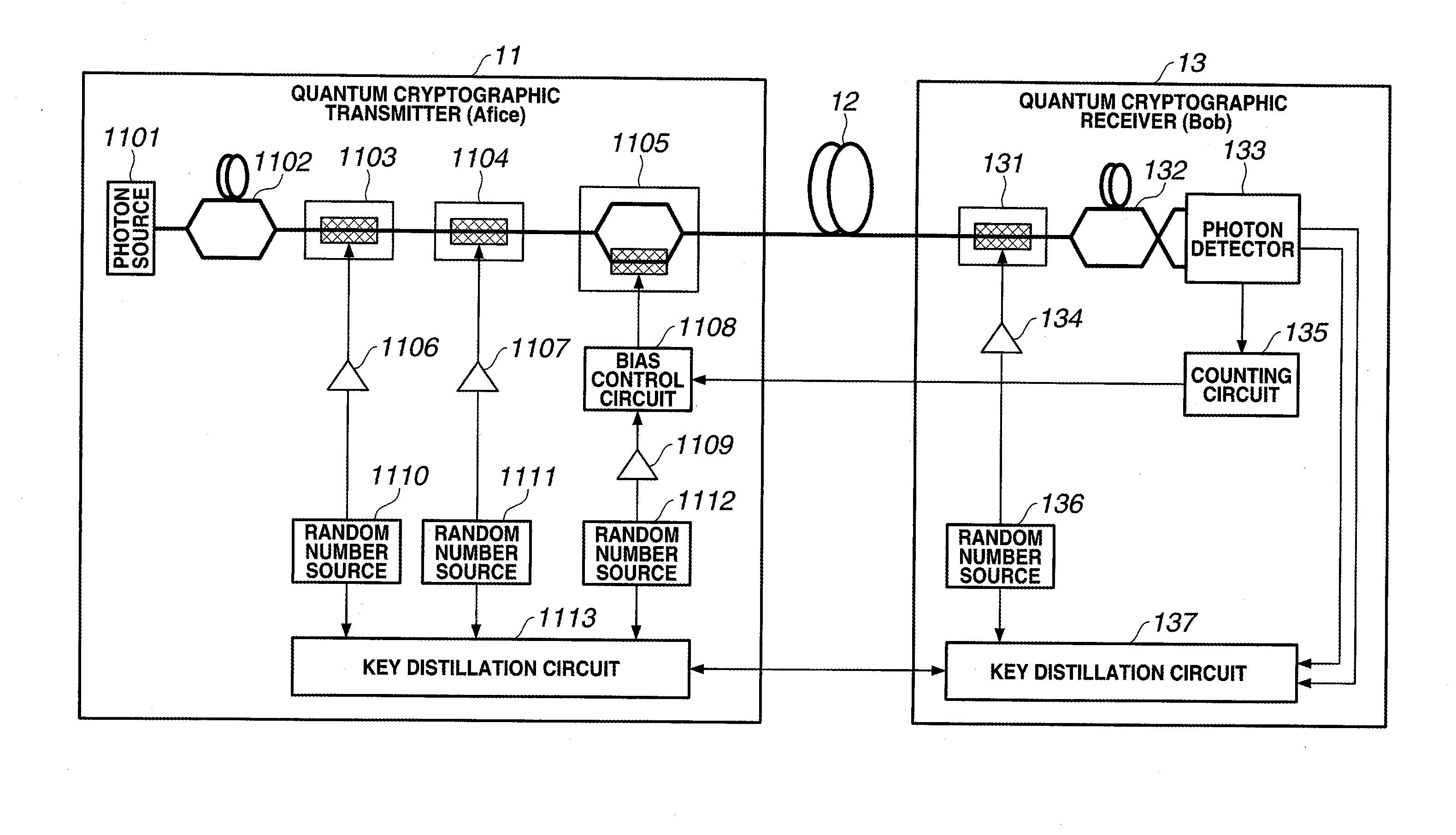
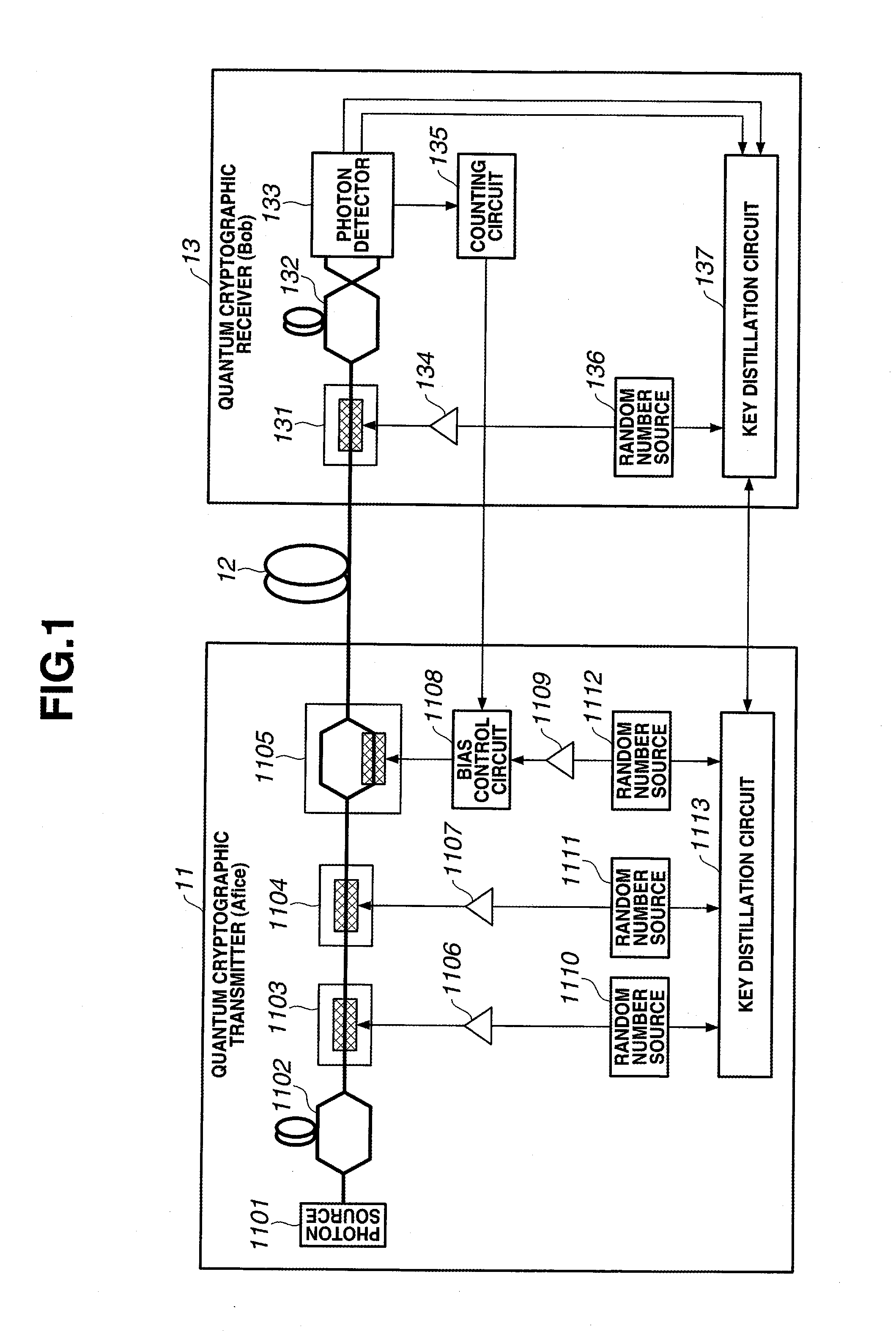
[0102]A conventional auto bias control circuit cannot control the bias of the light intensity modulator used in the quantum cryptosystem. The reason is as follows. In the conventional method, a monitor PD receives light output from the modulator, and bias control is executed based on the information of the optical signal after modulation. However, the quantum cryptosystem uses a low-intensity optical signal of single photon level, and it is therefore impossible to obtain modulated optical signal information using a monitor PD.

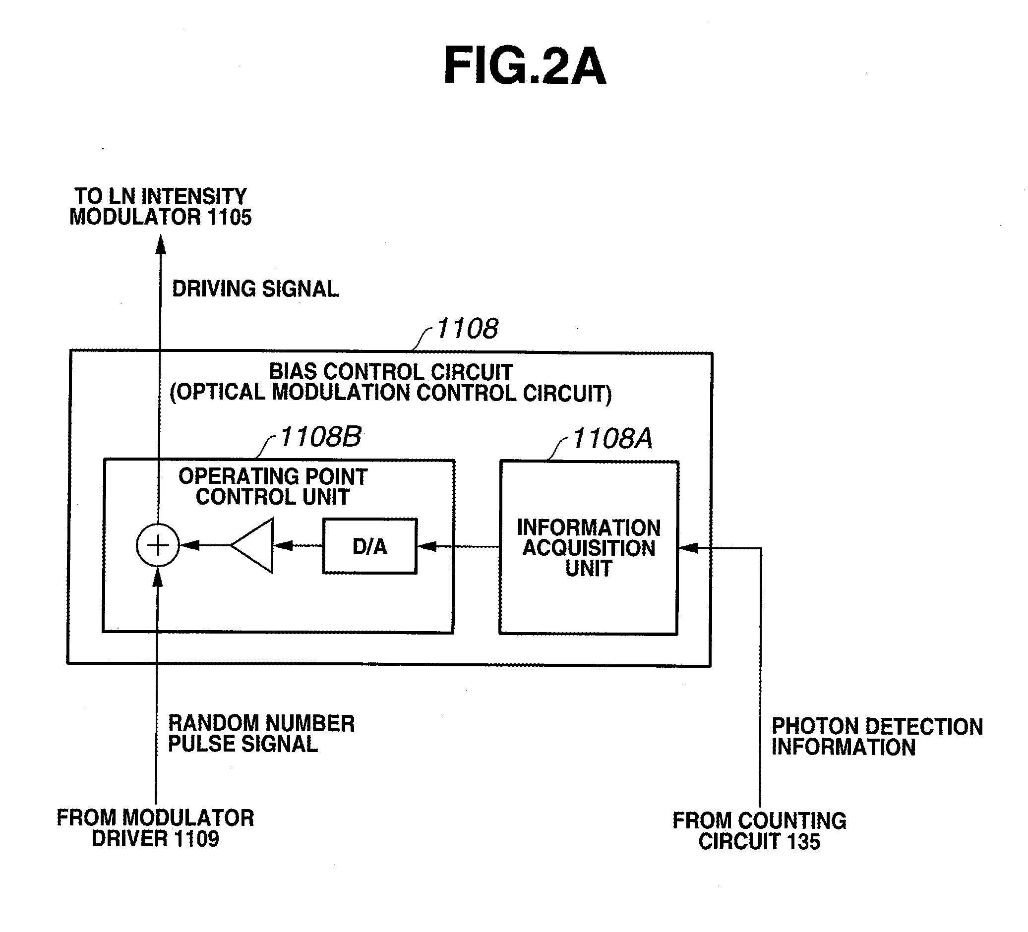
[0103]In this exemplary embodiment, the quantum cryptographic transmitter 11 causes the phase modulators 1103 and 1104 and the LN intensity modulator 1105 to perform optical phase modulation and light intensity modulation of an optical signal based on desired data, thereby generating a desired optical signal to be transmitted to the quantum cryptographic receiver 13. The bias control circuit 1108 controls the operating point...

second exemplary embodiment

Effects of Second Exemplary Embodiment

[0132]A conventional two-way quantum key distribution system cannot obtain information of output light using a simple monitor PD. Especially, when probe light as described in reference 8 is used, signal light of single photon level is buried in noise light such as Rayleigh scattered light or Raman scattered light regardless of whether the probe light and the signal light have the same or different wavelengths. A means for reducing signal light to the single photon level after monitoring a modulated signal at a sufficient light intensity in the quantum cryptographic transmitter is not applicable due to the following reason. The reason will be explained below.

[0133]In the two-way quantum key distribution system, the photon detector observes backscattered light of an optical pulse in the forward path as noise. Out of the backscattered light, Rayleigh scattered light without any wavelength change cannot be separated from signal light by a wavelength...


PUM


Abstract

In a quantum cryptographic transmitter (11), a phase modulator (1103, 1104) and an LN intensity modulator (1105) apply optical phase modulation and light intensity modulation to an optical signal based on desired data to generate a desired optical signal to be transmitted to a quantum cryptographic receiver (13). Based on the number of photons detected from the desired optical signal, a bias control circuit (1108) controls an operating point in light intensity modulation of the LN intensity modulator (1105).

Description

TECHNICAL FIELD[0001]The present invention relates to an optical modulation technique and, more particularly, to an operating point control technique when modulating the intensity of an optical signal.BACKGROUND ART[0002]Although the rapidly growing Internet is convenient, there is great apprehension about its safety, and the need for an advanced cryptographic technique is intensifying to keep the confidentiality of communications. Cryptographic methods commonly used at present are classified into secret key cryptography such as DES (Data Encryption Standard) and Triple DES and public key cryptography such as RSA (Rivest Shamir Adleman) and elliptic curve cryptography. However, these cryptographic methods guarantee the safety based on “complexity of calculations”. Code-breaking using an enormous amount of calculations and new decryption algorithms is an ever present danger.[0003]Under these circumstances, research has been done on quantum cryptosystems which integrate an information...

Claims


Application Information

Patent Timeline
IPC IPC(8): H04L9/08G02F1/01H04B10/04H04B10/548
CPCH04L9/0858H04B10/548
Inventor TANAKA, AKIHIROTAJIMA, AKIOTAKAHASHI, SEIGOMAEDA, WAKAKO
Owner NEC CORP
Why Eureka
Try Eureka