Selective catalytic reduction type catalyst, and exhaust gas purification equipment and purifying process of exhaust gas using the same

a catalytic reduction and catalytic reduction technology, applied in physical/chemical process catalysts, metal/metal-oxide/metal-hydroxide catalysts, separation processes, etc., can solve the problems of nh/sub>3/sub>itself harmful effects such as irritating odor, and it is difficult to properly inhibit the generation of harmful substances, etc., to achieve superior nox purification performance and nh3 purification performance. , the effect of high efficiency

Inactive Publication Date: 2010-08-05
N E CHEMCAT
View PDF4 Cites 48 Cited by
  • Summary
  • Abstract
  • Description
  • Claims
  • Application Information

AI Technical Summary

Problems solved by technology

However, it is not that, in all type of combustion engines, air and fuel can be always controlled in an ideal state, and large amounts of harmful substances such as nitrogen oxides are sometimes generated due to incomplete combustion.
Among them, in the case of a diesel engine that is mounted in an automobile, since its operation conditions always vary, it had been particularly difficult to properly inhibit generation of harmful substances.
In a denitration catalyst system utilizing such reaction mechanisms, gasified NH3 may be used as a reducing component, but NH3 itself has harmful effects such as an irritating odor, etc.
However, since the above-described catalyst to purify NH3 uses a noble metal component having a high oxidizing ability such as platinum, palladium, rhodium as a catalytically active species, there was a problem that the catalyst could cause the new generation of NOx component such as N2O, NO, NO2 in addition to the oxidation of NH3, as shown by the following reaction equations (5) to (7).
However, vanadium itself is a harmful heavy metal, and its use is not desirable because of a fear that it could vaporize into exhaust gas when used as a catalyst, therefore, some automobile catalyst manufacturers avoid using it.
Although purification of slipped NH3 proceeds by arranging a catalyst to oxidize NH3 in the subsequent stage in such a way, the process is accompanied by a risk that additional NOx is generated due to a presence of a highly active noble metal catalyst on the surface of the carrier, and cannot be regarded as satisfying one against the regulation for NOx which is becoming increasingly severe in recent years.
Although catalytic reaction is promoted in proportion to the surface area of a catalyst, the volume of catalyst to be loaded and its placement are limited in the case of automobile use, therefore, the measure to increase simply a volume of catalyst cannot be said to be a practical solution.
The filtered out combustible particle component deposits on the filter, and leads to the clogging of the filter, if the component is kept as it is.
However, since the combustion of combustible particle component is oxidation reaction even when NO2 is used, and a large amount of NO is contained in the exhaust gas exhausted after the combustion, some purification means for NOx is required in this method also.

Method used


Image

  • Selective catalytic reduction type catalyst, and exhaust gas purification equipment and purifying process of exhaust gas using the same
  • Selective catalytic reduction type catalyst, and exhaust gas purification equipment and purifying process of exhaust gas using the same
  • Selective catalytic reduction type catalyst, and exhaust gas purification equipment and purifying process of exhaust gas using the same

Examples


examples

[0154]Hereinafter, the features of the present invention will be further clarified by showing Examples and Comparative Examples. It should be noted that the present invention is not limited to the embodiments of these Examples. It should be noted that the catalysts used in Examples and Comparative Examples were prepared according to the methods described below.

[Production of SROC (1)]

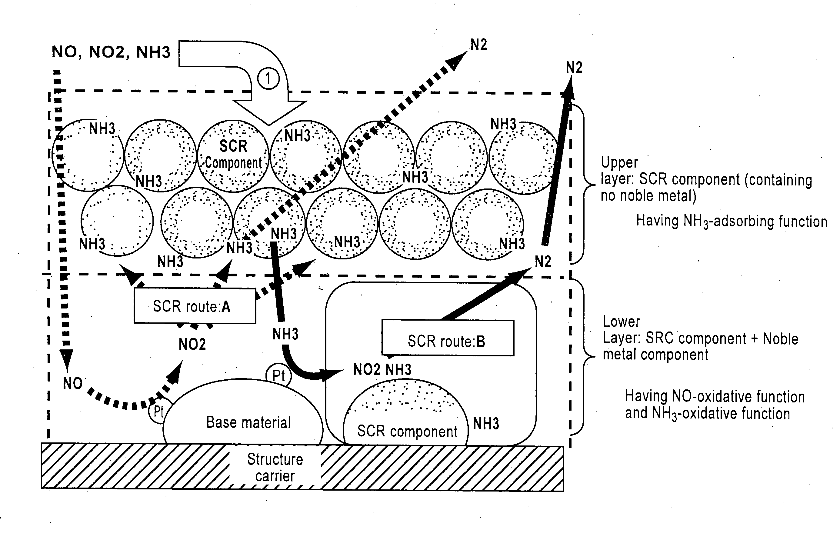
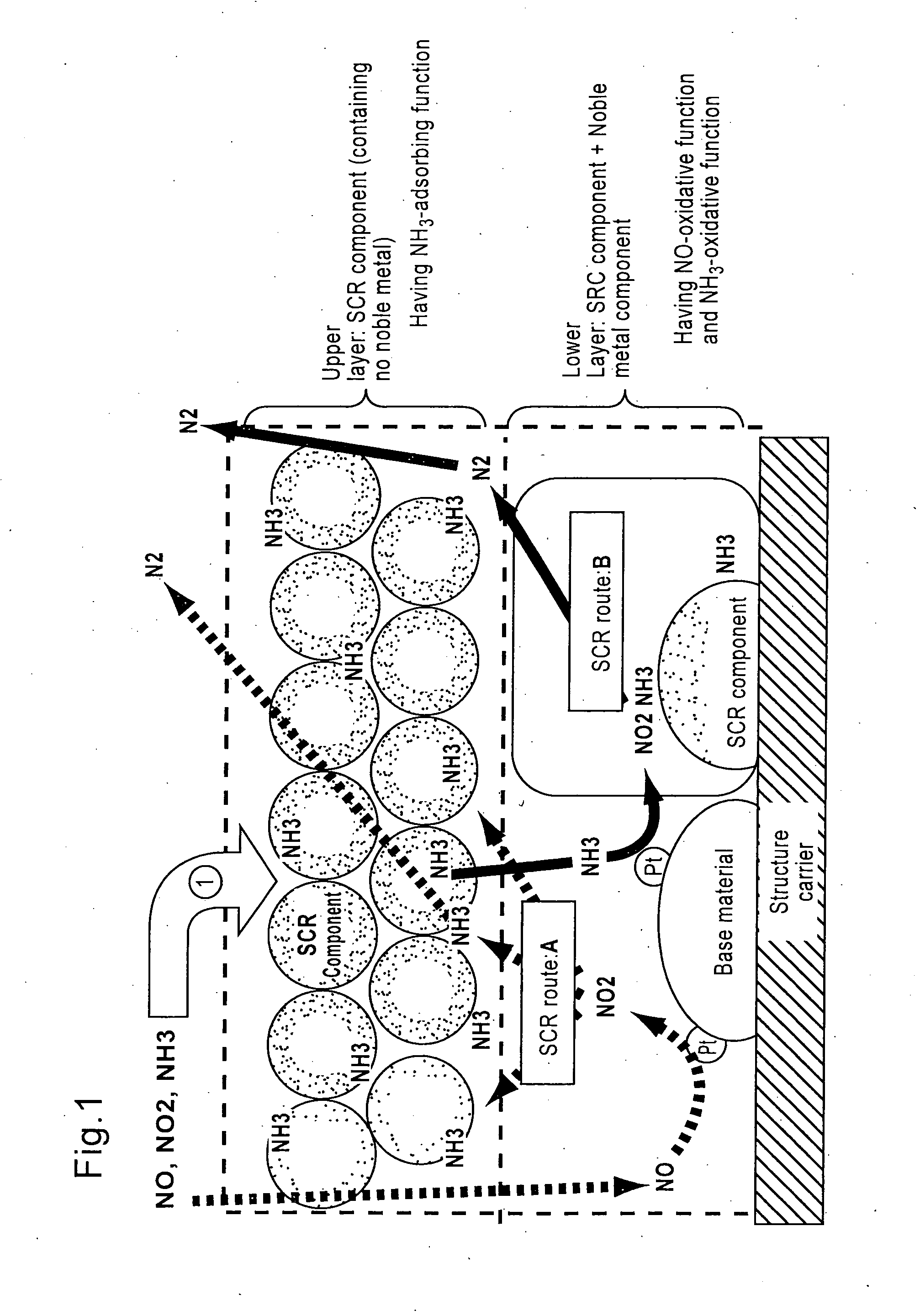
[0155]=Lower layer (catalyst layer having an oxidative function for NH3)=

[0156]Titania powder (BET value: 100 m2 / g) as a base material was impregnated with an aqueous platinic chloride solution as a raw material of noble metal component to support platinum (2.5% by weight in Pt equivalent), and the mixture was further added with water, β-type zeolite ion-exchanged with iron element (concentration: 2% by weight in iron element equivalent, ion-exchange percentage: 70%, SAR=40), and silica as a binder to adjust concentration, then milled in a ball mill to obtain a slurry of NH3-oxidation catalyst part. Thi...

examples 1 , 2

Examples 1, 2

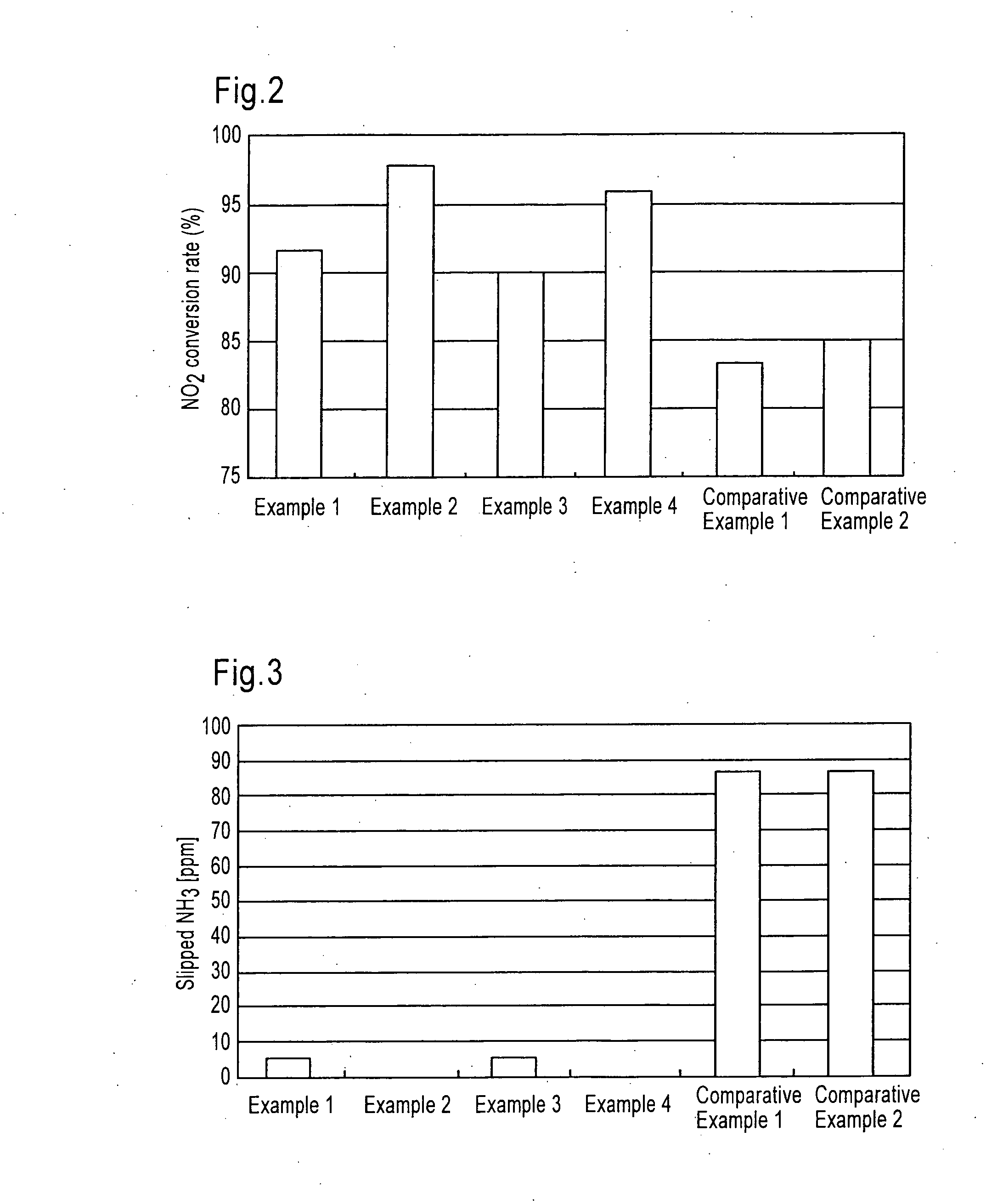
[0163]The selective catalytic reduction type catalyst of the present invention SROC (1) prepared as described above was arranged together with DOC in an exhaust gas pipe as shown below. (NH3) represents a position of supplying an urea aqueous solution as an ammonia component by spraying.

[0164]Example 1: DOC+(NH3)+SROC (1)

[0165]Example 2: DOC+(NH3)+SCR+SROC (1)

examples 3 , 4

Examples 3, 4

[0166]The selective catalytic reduction type catalyst of the present invention SROC (2) prepared as described above was arranged together with DOC in an exhaust gas pipe as shown below. (NH3) represents a position of supplying an urea aqueous solution as an ammonia component by spraying.

[0167]Example 3: DOC+(NH3)+SROC (2)

[0168]Example 4: DOC+(NH3)+SCR+SROC (2)


PUM

PropertyMeasurementUnit
thicknessesaaaaaaaaaa
volumeaaaaaaaaaa
temperatureaaaaaaaaaa

Abstract

The present invention is an exhaust gas purification catalyst equipment, and a method of use thereof, formed by arranging a selective catalytic reduction type catalyst for purifying nitrogen oxides in exhaust gas exhausted from lean combustion engines using ammonia or urea as a reducing agent, it is provided with a selective catalytic reduction type catalyst, characterized in that said catalyst comprises a lower-layer catalyst layer (A) having an oxidative function for nitrogen monoxide (NO) in exhaust gas and an upper-layer catalyst layer (B) having an adsorbing function for ammonia on the surface of a monolithic structure type carrier (C), and that the lower-layer catalyst layer (A) comprises a noble metal component (i), an inorganic base material constituent (ii) and zeolite (iii), and the upper-layer catalyst layer (B) comprises substantially none of component (i) but the component (iii), in a flow path of exhaust gas, characterized in that a spraying means to supply an urea aqueous solution or an aqueous ammonia solution is arranged in the downstream of the aforementioned oxidation catalyst and in the upstream of aforementioned selective catalytic reduction type catalyst.

Description

[0001]This application is a Continuation-in-Part application of U.S. application Ser. No. 12 / 149,575, filed May 5, 2008, and claims the right of priority under 35 U.S.C. §119 based on Japanese Patent Application No. 2007-124152 filed May 9, 2007, which is hereby incorporated by reference herein in its entirety as if fully set-forth herein.TECHNICAL FIELD[0002]The present invention relates to a selective catalytic reduction type catalyst, and an exhaust gas purification equipment and a purifying process of exhaust gas using the same. In more detail, the present invention relates to a technology to purify nitrogen oxides contained in exhaust gas exhausted from lean combustion engines such as diesel engines with ammonia and a selective catalytic reduction catalyst, and provides a selective catalytic reduction type catalyst which can effectively purify nitrogen oxides even at a low temperature as well as inhibit leaking of ammonia, and an exhaust gas purification equipment and a purifyi...

Claims


Application Information

Patent Timeline
Patent Type & Authority Applications(United States)
IPC IPC(8): B01D53/94B01D50/00
CPCB01D53/925Y02T10/24B01D53/9436B01D53/944B01D53/9468B01D2251/2062B01D2251/2067B01D2255/1021B01D2255/1023B01D2255/1025B01D2255/206B01D2255/20707B01D2255/20715B01D2255/20738B01D2255/20776B01D2255/2092B01D2255/30B01D2255/502B01D2255/504B01D2255/9022B01D2255/9027B01D2255/91B01D2255/911B01D2258/012B01J21/063B01J21/066B01J23/42B01J23/63B01J29/46B01J29/7615B01J37/0244B01J37/0246B01J37/0248B01D53/9418Y02T10/12
Inventor ANDO, RYUJIHIHARA, TAKASHIKANNO, YASUHARUNAGATA, MAKOTO
Owner N E CHEMCAT
Why Eureka
Try Eureka