Systems and methods for detecting a signal and applying thermal energy to a signal transmission element

a signal transmission element and thermal energy technology, applied in the field of multichambered receptacles, can solve the problems of inability to document, inability to carry out naat assay instruments, and limited use in large-scale testing in controlled environments, so as to reduce the chance of contamination and reduce the cost

Active Publication Date: 2010-08-05
GEN PROBE INC
View PDF45 Cites 42 Cited by
  • Summary
  • Abstract
  • Description
  • Claims
  • Application Information

AI Technical Summary

Benefits of technology

[0005]The present invention provides compact instruments, detectors and associated receptacles and processes for performing complex procedures, such as sample-to-result NAAT assays, that permit point-of-use testing at substantial cost savings to conventional, large-scale instrument systems. The receptacles include interconnected chambers that can be prepackaged in unit dose form with all of the reagents needed to perform an assay. The receptacles are closed systems that minimize opportunities for contamination.

Problems solved by technology

No document, however, is admitted to be prior art to the claimed subject matter.
In general, however, instruments used to perform NAAT assays are not easily portable and their usefulness is typically limited to large-scale testing in controlled environments.

Method used


Image

  • Systems and methods for detecting a signal and applying thermal energy to a signal transmission element
  • Systems and methods for detecting a signal and applying thermal energy to a signal transmission element
  • Systems and methods for detecting a signal and applying thermal energy to a signal transmission element

Examples


example 1

Manual Amplification Reactions

[0398]For this experiment, manual TMA reactions were set up in 12×75 mm polypropylene reaction tubes (Gen-Probe Incorporated, San Diego, Calif.; Cat. No. 2440), and each reaction tube was provided with 125 μL of a Target Capture Reagent containing 160 μg / mL 1 micron magnetic particles Sera-Mag™ MG-CM Carboxylate Modified (Seradyn, Inc.; Indianapolis, Ind.; Cat. No. 24152105-050450) derivatized with poly(dT)14 and suspended in a solution containing 250 mM HEPES, 310 mM LiOH, 1.88 M LiCl, 100 mM EDTA, adjusted to pH 7.5, and 10 pmol / reaction of the wobble capture probe. Each reaction tube was then provided with 500 FL of a mixture containing a Sample Transport Medium (150 mM HEPES, 294 mM lithium lauryl sulfate (LLS) and 100 mM ammonium sulfate, adjusted to pH 7.5) and water in a 1-to-1 ratio. The mixtures contained either 105 copies of the target nucleic acid (test samples) or no target nucleic acid (negative control samples). The reaction tubes were cov...

example 2

Automated Amplification Reactions in a Multi-Chambered, Flexible Receptacle Using Liquid Reagents

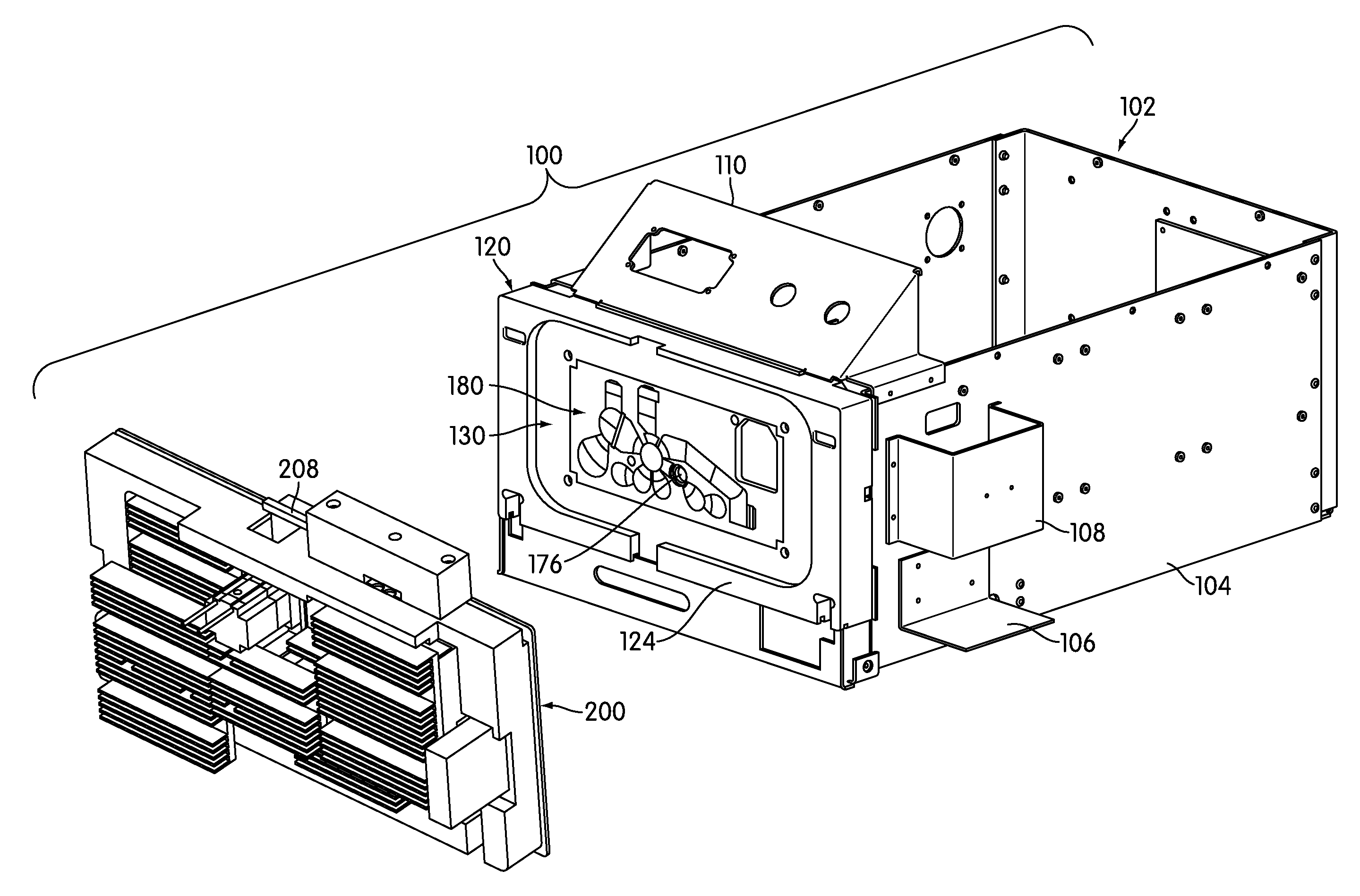
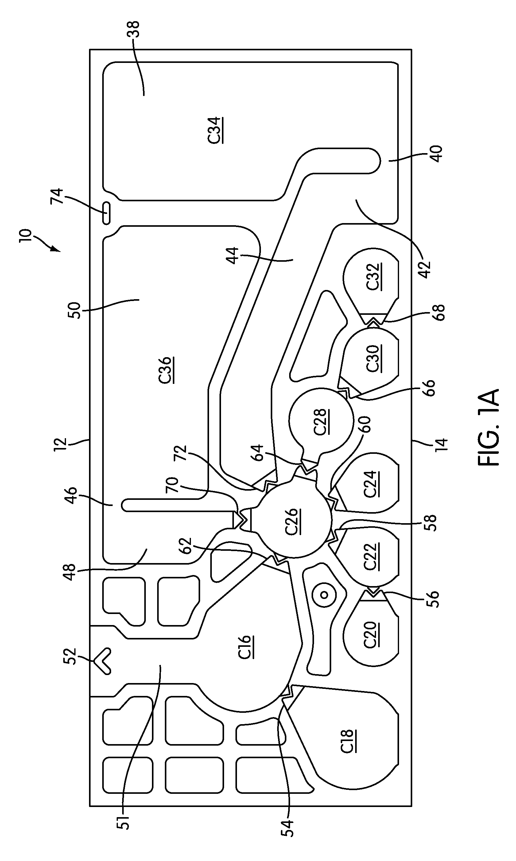
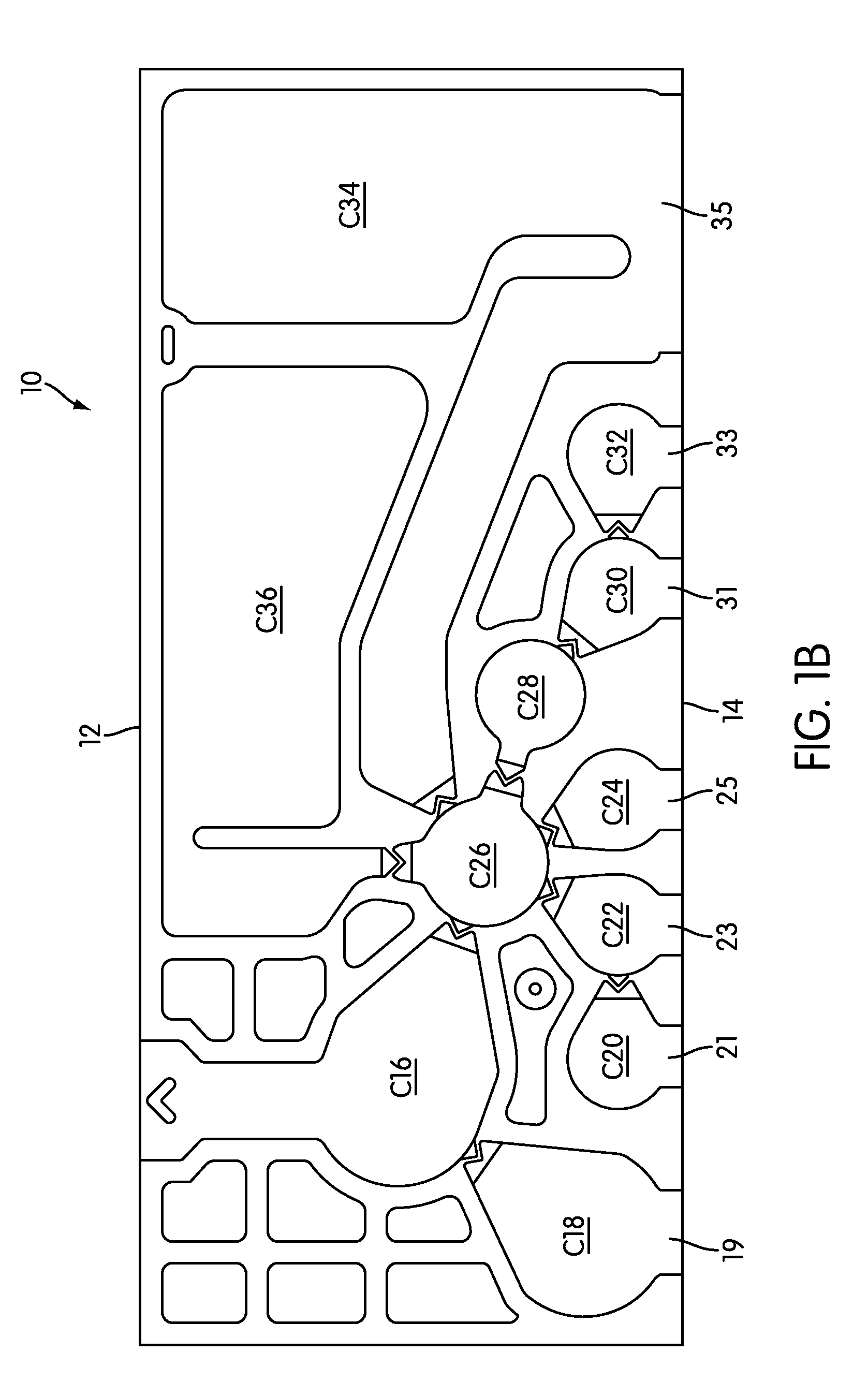
[0402]In this experiment, the TMA reaction of Section 1 of this example was performed using the receptacle 10 and instrument 100 illustrated in FIGS. 1A and 3. The receptacle 10 illustrated in FIG. 1B was pre-loaded with reagents in the following manner: (i) 125 μL of the Target Capture Reagent was added to chamber C18; (ii) 3 mL of the Wash Buffer was added to chamber C34; (iii) 25 μL of the Oil Reagent, followed by 85 μL of the Amplification / Detection Reagent, was added to chamber C20; and (iv) 35 μL of the Oil Reagent, followed by 25 μL of the Enzyme Reagent, was added to chamber C32. After reagent loading, all of the chambers of the receptacle 10 except chamber C16 were closed by heat sealing. A 500 μL test sample having 105 copies of the target nucleic acid, as described in Example 1 above, was then pipetted into chamber C16, the sample chamber, which was then closed by heat sealing...

example 3

Automated Amplification Reactions in a Multi-Chambered, Flexible Receptacle Using Liquid Reagents and a Urine Samples

[0411]This experiment was designed to evaluate a real-time TMA reaction using a urine sample spiked with 105 copies of target nucleic acid. The materials and methods of this experiment were the same as those of the real-time TMA reaction described in Example 2, with the following exceptions: (i) chamber C18 was loaded with 150 μL of the Target Capture Reagent containing 10 pmol of the wobble capture probe in combination with 100 μL of water; (ii) chamber C34 was loaded with 2 mL of the Wash Buffer; (iii) the Oil Reagent was not loaded into chamber C20 or chamber C32 prior to loading the Amplification / Detection and Enzyme Reagents into these chambers; (iv) the test sample included 250 μL of urine from a healthy donor and 250 μL of the Sample Transport Medium; and (v) the steps of moving the TCR / sample mixture from chamber C16 to chamber C26, subjecting the magnetic par...


PUM

PropertyMeasurementUnit
pore sizeaaaaaaaaaa
thicknessaaaaaaaaaa
thicknessaaaaaaaaaa

Abstract

A signal detection system configured for detecting a signal emitted by the contents of a reaction receptacle is also configured to apply thermal energy to a portion of the reaction receptacle to affect a reaction occurring within the reaction receptacle. More particularly, a system for detecting electromagnetic radiation emitted by the contents of a reaction receptacle includes a transmission element configured for transmitting electromagnetic radiation from the contents of the receptacle, a thermal element associated with the transmission element and configured to apply thermal energy to at least a portion of the receptacle, and a detector configured to receive electromagnetic radiation from the transmission element and to generate a signal corresponding to a characteristic of the electromagnetic radiation received by the detector.

Description

[0001]This application claims the benefit under 35 U.S.C. 119(e) of U.S. Provisional Application No. 61 / 148,587, filed Jan. 30, 2009, the disclosure of which is hereby incorporated by reference in its entirety.FIELD OF THE INVENTION[0002]The present invention relates to multi-chambered receptacles and associated instruments and detection devices for use in performing complex processes.BACKGROUND OF THE INVENTION[0003]All documents referred to herein, or the indicated portions, are hereby incorporated by reference herein. No document, however, is admitted to be prior art to the claimed subject matter.[0004]Highly sophisticated instruments have been developed for performing complex assays requiring multiple process steps to be performed simultaneously and independent of each other. Such instruments can be used to perform chemical analyses, immunoassays, molecular-based tests, and the like. The most advanced of these instruments are capable of performing sample-to-result, nucleic acid-...

Claims


Application Information

Patent Timeline
Patent Type & Authority Applications(United States)
IPC IPC(8): C12Q1/68G01N21/64H01L31/09H01L31/0232C12M1/34
CPCB01L3/5027G01N2021/0346B01L7/52B01L9/527B01L2200/04B01L2200/146B01L2300/021B01L2300/044B01L2300/0654B01L2300/0672B01L2300/0816B01L2300/087B01L2300/1827B01L2400/043B01L2400/0478B01L2400/0481B01L2400/0487B01L2400/0605B01L2400/0666G01N21/03G01N21/0332G01N2021/0328G01N2035/00346B01L3/505
Inventor OPALSKY, DAVIDWALKER, GEORGE T.NELSON, NORMAN C.LEE, RICHARD S.FAN, SARA H.
Owner GEN PROBE INC
Why Eureka
Try Eureka