Automatic estimation of weldgun size using section geometry

Active Publication Date: 2010-08-05
GM GLOBAL TECH OPERATIONS LLC
View PDF8 Cites 3 Cited by
  • Summary
  • Abstract
  • Description
  • Claims
  • Application Information

AI Technical Summary

Problems solved by technology

However, this method is time consuming and also requires manual iterations for selecting the correct weld gun.
Further, the weld gun selected using this method can fail while validating the weld gun for all the weld points of a welding operation.
Moreover, the me

Method used


Image

  • Automatic estimation of weldgun size using section geometry
  • Automatic estimation of weldgun size using section geometry
  • Automatic estimation of weldgun size using section geometry

Examples


Embodiment Construction

[0019]The following discussion of the embodiments of the invention directed to a method for estimating the geometrical parameters defining the size of a weld gun suitable for a welding operation is merely exemplary in nature, and is in no way intended to limit the invention or its applications or uses.

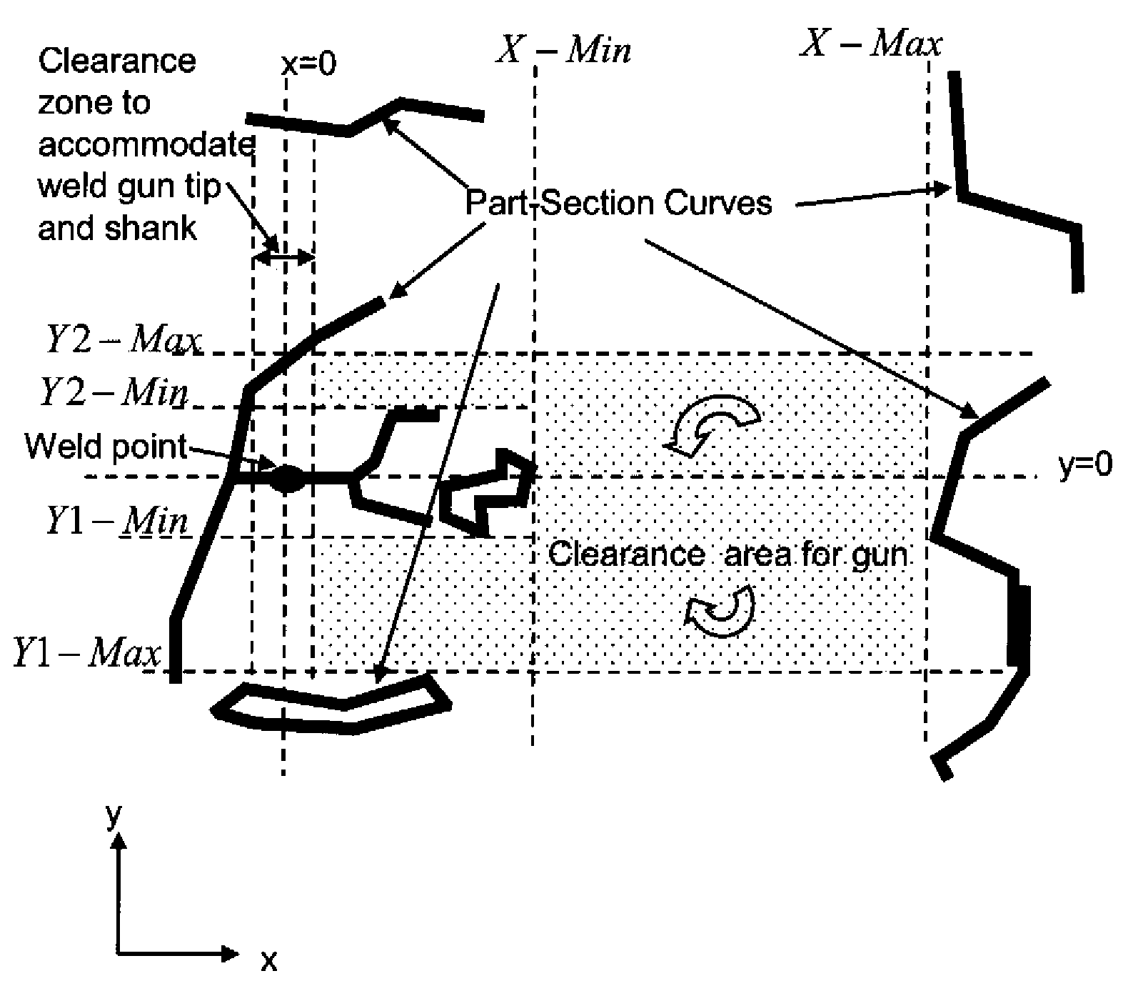
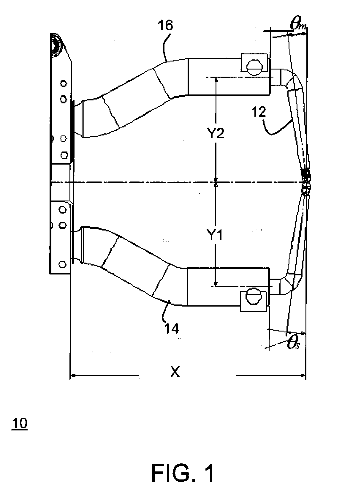
[0020]FIG. 1 depicts a throat area 10 of a weld gun illustrating a plurality of geometric parameters that define the throat area 10. For the purpose of this description, a pinch (P) type weld gun has been used. The plurality of geometric parameters include the tip angles θs for a stationary arm 14 and θm for a moving arm 16 of the weld gun, an arm stick-out X of the weld gun, an arm offset Y2 of the moving arm 16 of the weld gun and an arm offset Y1 of the stationary arm 14 of the weld gun. The space available around the various weld points in a welding operation largely decides the various dimensions of a weld gun that would be suitable for the particular welding operation. Hence, the...


PUM


Abstract

A method for estimating a plurality of geometrical parameters defining the size of a weld gun that has particular application for automatically selecting a weld gun for a welding operation. The method includes iteratively estimating a plurality of geometric parameters based on part section curves corresponding to a direction of approach of the weld gun to weld point of the plurality of weld points. Thereafter, a set of valid weld gun sizes are calculated based on the estimated plurality of geometric parameters. Similarly all the valid weld gun sizes are calculated corresponding to each of the weld gun approach direction. Further, each set of the valid gun sizes are estimated for each of the weld point for the welding operation. Finally, a weld gun for performing the welding operation is selected based on the set of weld gun sizes corresponding to the welding operation.

Description

BACKGROUND OF THE INVENTION[0001]1. Field of the Invention[0002]This invention relates generally to a method for automatically selecting a welding gun for a welding operation and, more particularly, to a method for estimating the geometrical parameters defining the size of a welding gun suitable for a welding operation.[0003]2. Description of the Related Art[0004]Welding is sometimes performed to join two parts together. There are various types of welding technique, such as electric arc welding and resistance spot welding. Resistance spot welding is the most common joining operation used in automotive assembly line. In resistance spot welding process, the welding is performed by placing the parts to be joined together between the electrodes of a weld gun and an electric current is passed through the electrodes. The parts are welded due to the high temperature caused by the resistance to electric current flow of the electrodes. In an automotive assembly line, parts are joined at vari...

Claims


Application Information

Patent Timeline
IPC IPC(8): G06F19/00G06F17/10
CPCB23K11/314
Inventor GUPTA, ASHISHSHASTRY, GOPALAKRISHNAHUNSUR, NARAHARI K.
Owner GM GLOBAL TECH OPERATIONS LLC
Why Eureka
Try Eureka